The best way to learn anything new is by doing it with your own hands, eyes and mind. You will learn the quickest with Halogen running in another window, and Alt-Tab to alternate with this page in your browser window. You can also print a PDF of this tutorial and run Halogen full screen, If you don’t already have Halogen installed, download it here. The finished application and a downloadable configuration file are here.
The first thing is deciding the kind and size of system you want to build. Any system design starts by choosing the best equipment fit. Think of the answers to these questions as you select one of the four HAL Multiprocessors:
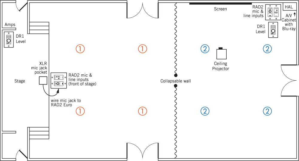
Let’s build a sound system for a school auditorium or church multipurpose room. There is a stage at one end and a moveable wall to split the room. The opposite end is sometimes a meeting room with its own mic and A/V. Here’s the floor plan of the room, divider and the existing stage mic input in a floor pocket. The new system is easy to understand and operate.
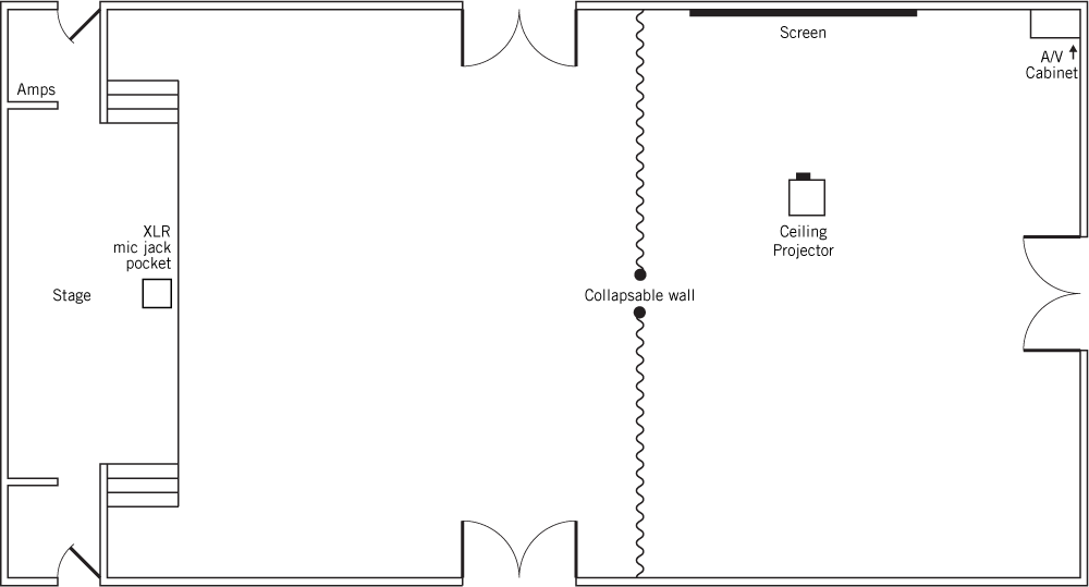
There are several ways to make a successful system for this room. It all depends on what you want it to do. The system has these requirements:
We come up with six inputs and two loudspeaker zones. So now let’s decide on the best HAL.
Every HAL system requires one HAL base unit to start with. HAL options are easily compared next to each other. Launch Halogen, and in the top File toolbar, choose New, and then Choose HAL Model Configuration. Hover your mouse over the four models to see the ins and outs of each. The HAL1x and HAL2 may look similar, but if you need more inputs, outputs, RAD ports, Dante or AEC, choose the HAL1x which lets you add Expanders.
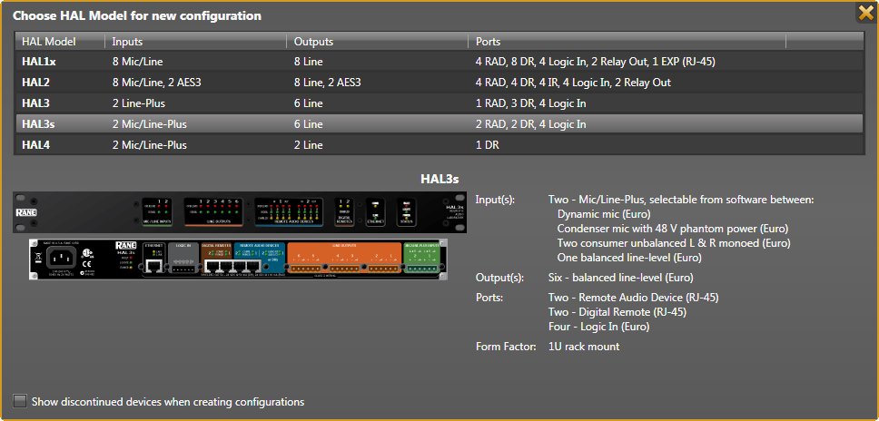
Remote Audio Device (RAD) ports are each capable of two inputs and two outputs, depending on the RAD model. So add the RAD port inputs and outputs to HAL inputs and outputs to find the total I/O capability.
The HAL3s only has two inputs, but gives us the six inputs we need when we include the RAD ports, so it’s the best candidate. After choosing the HAL3s, the Hardware workspace appears.
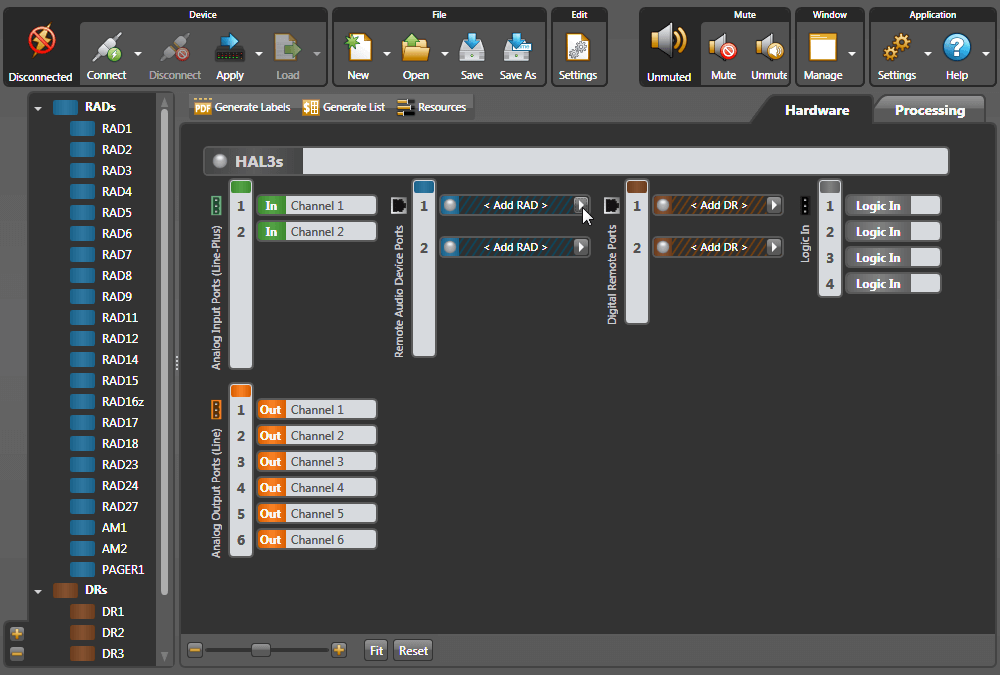
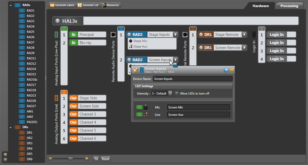
Let’s add the RADs for the additional “distant” audio inputs we need. You can hover your mouse over the blue RAD models on the left to get a brief description, and then drag the model over. But there’s a better way. In the workspace, click the white triangle at the right end of the black and blue < Add RAD > bar on Port 1. This brings up a detail list with the input and output type of each RAD along with a picture. The RAD2 gives me the mic and line inputs I want for the stage. The existing stage mic XLR can be wired to the Euroblock on the back of the RAD2. Click on the RAD2 line to virtually install this RAD on Port 1. Once selected, this informs the HAL3s to expect the RAD2 model to physically be plugged into the same port when it is installed.

After building a system in Halogen, if you want to try a different RAD, come back to this Port arrow and replace the RAD. For instance, if I figure out later that an RAD7 or RAD16z would work better than the RAD2, I can quickly change it here. Isn't it nice to quickly swap this out before buying any hardware?
We need another RAD2 for the mic and line inputs at the screen side of the room. Click on the next empty < Add RAD > white arrow, and choose another RAD2 for this port.
Let’s add the control remotes so the volume can be operated from either end of the room when the wall is open, and independently when the wall is closed. These are added just like the RADs. Click the white arrow at the right end of the black and brown < Add DR > bar. Choose the DR1 for Port 1, which mounts backstage out of the audience view.
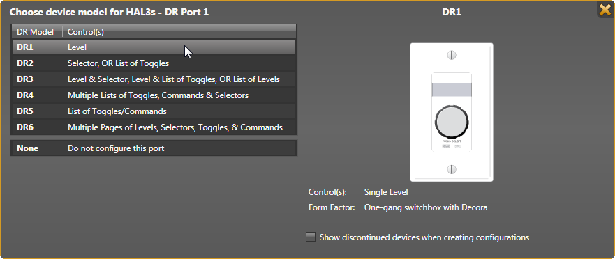
For Port 2, choose another DR1 to be located by the screen. This remote can mount inside or outside the A/V cabinet for the security level desired.
![]() Now let’s name all the connections in the hardware workspace. This helps verify all the ins, outs, and controls are accounted. Hover your mouse over the name in a white block of an In, Out, RAD or DR. Click, and you’ll get a text edit box; click inside to get an I-beam edit cursor once it is in an editable region. The keyboard’s Enter (Return) commits the label.
Now let’s name all the connections in the hardware workspace. This helps verify all the ins, outs, and controls are accounted. Hover your mouse over the name in a white block of an In, Out, RAD or DR. Click, and you’ll get a text edit box; click inside to get an I-beam edit cursor once it is in an editable region. The keyboard’s Enter (Return) commits the label.
Name each analog input (green). The Principal’s office intercom feed connects to Input 1, and the Blu-ray player audio connects to Input 2.
Only two speaker zone outputs are needed. Name one output for feeding the stage side amplifier, and the other for the screen side amplifier. Extra outputs are available for future recording or another zone. Just use what’s needed for now.
When hovering over a RAD or DR name, a white daisy appears right of the name. Clicking the daisy opens additional unique settings along with the name. For instance, the RAD2 lets you name the individual inputs. Naming these now will help you differentiate from the other RAD2 inputs. The RAD LED or DR backlight settings can be changed here. When you eventually connect to a live HAL device, the properties also include a status bar below the RAD name as well as a Locate button and a device serial number. This information quickly helps you locate and fix any port or cable errors.
As with any software, it’s always smart to save your work as you go. In the top menu, File > Save As works like any other program. Save regularly as you finish sections. Any time during this tutorial you need more explanation than what’s here, click the ![]() Help button at the upper right of any dialog or window.
Help button at the upper right of any dialog or window.
With the inputs and outputs determined, here’s an updated floor plan with RADs, DRs, and speaker zones 1 and 2.
The first time you click the Processing tab (upper right) a page of instructions appears. We’ll follow these with more explanation, in the same order, for those reading while Halogen is open. This instructional text disappears as soon as you add a block to the workspace.
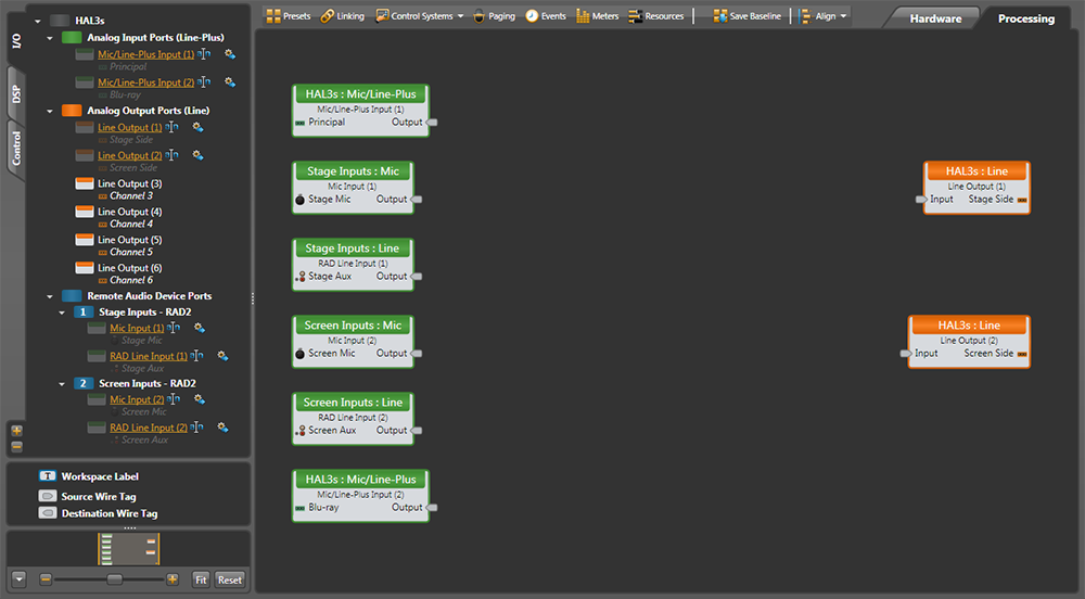
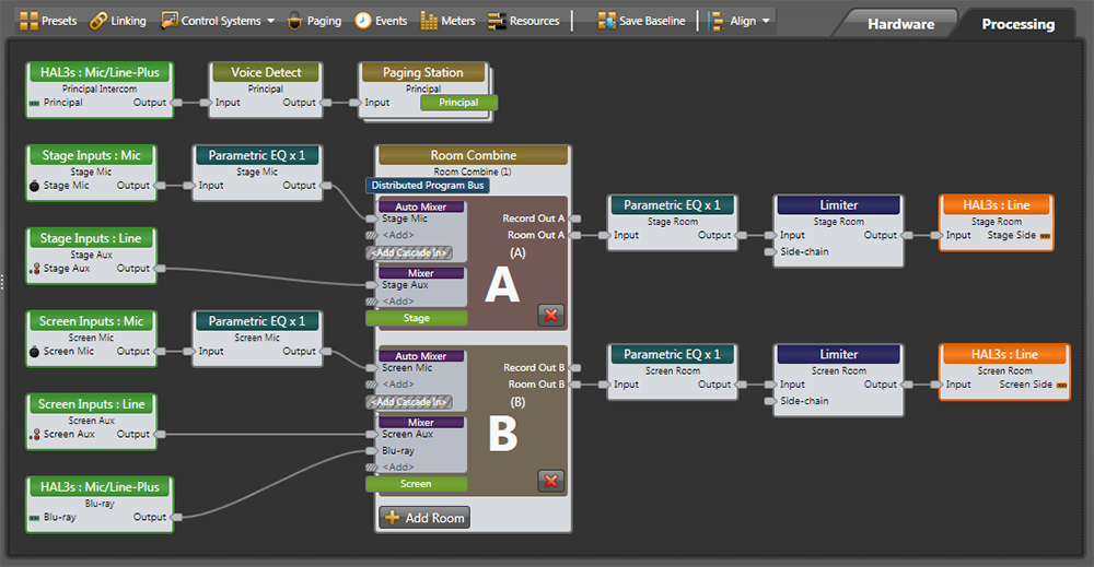
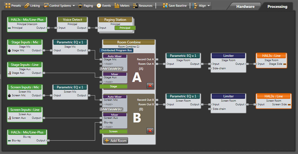
Let’s set up the basic audio routing and processing for the auditorium. Open the I/O tab in the palette to the left. Drag and drop the named Input and Output blocks to the workspace. Holding down Shift lets you select multiple blocks for simultaneous dragging. Place inputs (green) at the left, outputs (orange) toward the right, and leave room for DSP in the middle. After an I/O block is dragged to the map, it goes gray in the I/O palette, easily showing what’s used and what’s not. Don’t pull in leftover inputs or outputs; if a year later you need a record output, it’s easy to add. I’m putting the principal’s page input at the top, the stage inputs next, and the screen inputs next. You can place your inputs and outputs any way that helps you keep track of them, and move them as you go.
A big plus of working with Halogen is in helping you build real-world audio systems. It provides applications-level DSP blocks, not just disparate parts and pieces that must be manually wired together then finagled repeatedly to create predictable system behaviors. This makes dense systems easier to understand because every possible switchable I/O configuration isn’t cluttering up your design: less dragging and dropping, less manual virtual wiring, and less design time. There are many ways to configure Halogen and get the same result. The more you use Halogen, the more you will become aware of your options at hand.
Matrix Mixers are how traditional room combine systems are built. We could use a Preset that enables all the crosspoints to pass all inputs to both zones, and another Preset that disables crosspoints of inputs to the opposite side of the room. Halogen Presets memorize all the settings with a processing block, creating recallable snapshots. Multiple Presets can be more difficult to conceptualize. For your first system, let’s use the easier tools Halogen provides.
Halogen’s Room Combine block is easy to configure. It allows you to think about the sound in one room at a time, rather than having to think about how all the other rooms and remotes behave with each wall change. Paging multiplies the complexity in other systems, but the Room Combine block makes it easily manageable.
Open the DSP tab on the left, and drag in blocks following a traditional audio signal path, left to right, in this order:
 Input nodes are on the left and Output nodes are on the right of each block. Leave a little space between them for the wires we'll connect.
Sure, you’ll see lots of other free DSP to use, but let’s keep the audio chain short here for ease of understanding. Halogen lets you easily add DSP later.
Uh-oh, it’s already going to get crowded. I already see there won’t be room to fit in the room processor, parametric and limiters. No problem, the workspace is easy to expand and rearrange. Expand the overall Halogen window on your screen (or maximize your Window). Click-drag around the orange output blocks until they are highlighted, and then move them all as a group to the right (clicking on any one moves the group). Notice at the bottom left is a zoom slider control, and a Fit button that gets you back to full and center. You can do this at any time, and after the blocks are wired.
When you drag in the Room Combine block, it’s default is three rooms — we only want two. Click the “red x” ![]() in the “C” room to eliminate the third room.
in the “C” room to eliminate the third room.
Let’s place the blocks for the paging system from the Principal’s office along the top. This input comes from the first Mic/Line-Plus Input on the back of the HAL3s, fed by a long line and a transformer. After the page input, we’ll need these:
Name the blocks before wiring them. Naming is easy: just hover over the label, click and type. Names help keep your signals straight when wiring. With the multiple Parametrics and Levels here, the label helps you adjust the right one. Copy and Paste works with labels, if this saves you typing the same name (highlight the source name, Ctrl-C to copy, Ctrl-A to select all of the destination name, and Ctrl-V to paste).
Let’s wire the blocks together. Click and release on a block output node and then connect it to the input node of another block with a second click. One output can feed multiple inputs, but combining inputs requires a mixer block. You can move blocks around to get wires to look better or straighter. Right-click any wire to get cut, copy or delete commands.
There are wire-dressing techniques for deleting and replacing wires. If you want to delete a wire, click the middle of it to highlight in yellow, and hit your Delete key. If you start creating an unwanted wire, hit the Esc key so it turns yellow, then hit Delete. If you want to delete several wires at once, hold down the Ctrl key while you select each wire, then hit Delete.
Notice that as you wire to an input on a Mixer (or other expandable input block) it invites you to <Add> another node if it is needed. Add an input for the Blu-ray in the “B” room, which is the screen side of the room. Name any added inputs on the Mixer. Name these inputs as you wire them.
If you’re working on a map and you want more room in any area, it’s not a problem. Click-drag to highlight the group of input blocks, and pull them any direction to make room; the wires extend and screen shifts. Here’s what we have:
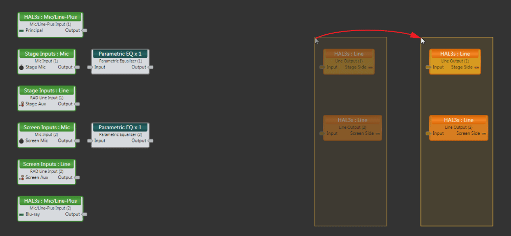
We’ve kept this system simple to make it easy to read. However, wiring lots of inputs to mixers and selectors can get messy, wires can overlap blocks and wires can cross. To make the wires snap to a grid, turn Smooth Wires off (in the Settings drop-down at the upper right). With Orthogonal on, wires are only drawn as horizontal and vertical. To make corners, click on an empty place in the background to place a vertex, which is like a staple holding the wire so you can route the wire around blocks. To create a visible connection node in the middle of a wire (e.g., split an output), instead of starting the wire from an output node, start at an input node and connect mid-wire, creating a vertex. Here’s the same map with smooth wires off and straight orthagonal lines.
Seeing all wire paths will get increasingly difficult as you add mixers and zones to larger maps. In more complex systems, you might need to locate a block or a sub-system on a far part of the screen, making linear 2D wires hard to trace and complicated to wrap. To illustrate this, I’ll delete the wires around the Room Combine block, and rearrange it away from the output chain. Creating a sub-system in a separate area of the processing screen can help clarify a large system.
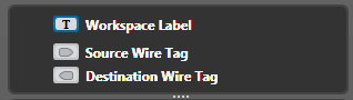 To make wire tracing easier, Halogen has color-coded wire tags. These are like color-coded rabbit holes. Below the palette on the left, you’ll see a Source Wire Tag and a Destination Wire Tag.
Drag a Source Wire Tag from the left column over to the processing map near an Output node of one of the Levels, and connect it with a wire. Hover over the Tag, click the daisy, enter a name, and choose a Background color that is easy to see. You can also change the Font color when the background color chosen makes reading the name difficult. Make Source Tags for the other Input source Output nodes in contrasting colors. Here I made five Sources: blue, green, yellow, orange and red, plus purple and teal for the Room Combine outputs.
Add a Destination Wire Tag near an Input node of the Room Combine Mixer, and connect it with a wire. Hover over it, and at the right end you’ll see a down-arrow. Click on that, and see a list of the sources you made. Select a source here, and the tag adopts the name and color of its Source. Continue to add Destination Tags for the inputs that need Source Tags. Now you can see the same color tags are connected, even if they are far apart.
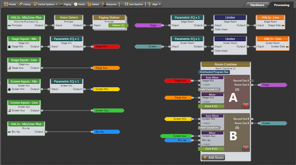
Notice there isn’t an Output node on the Paging Station. The lime green bar on the Paging Station connects through the Paging Manager to the lime green Zone bars in the “A” and “B” rooms in the Room Combine block. These are built-in lime green Wire Tags for paging sources (sticking out to the right side of the block) and destinations or zones (sticking out to the left of the blocks). Let Halogen’s Paging Manager do the page routing in the background, it’s much smarter and easier to build systems this way.
Name the lime green tags by clicking on them, and then we’ll set up the Paging Manager.
Click the Paging icon above the Processing Map Toolbar to open the Paging Manager. It already knows you have one page Station and two paging Zones. If you didn’t name the lime green tags yet, you can name them here.
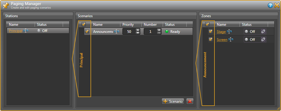
In this installation, there is only one Scenario — when the Principal has an announcement. Click on + Scenario at the bottom. Edit the name of this to be Announcement. Tick the box in this row. Under Zones, tick the boxes by both the Stage and Screen since we want this page heard in both zones. Ticking the box at the top selects all zones.
To test this, open the Paging Station dialog by double-clicking its title bar. Click your mouse on the Talk checkbox to check and uncheck, and watch the Paging Manager Zones turn Active and Off.
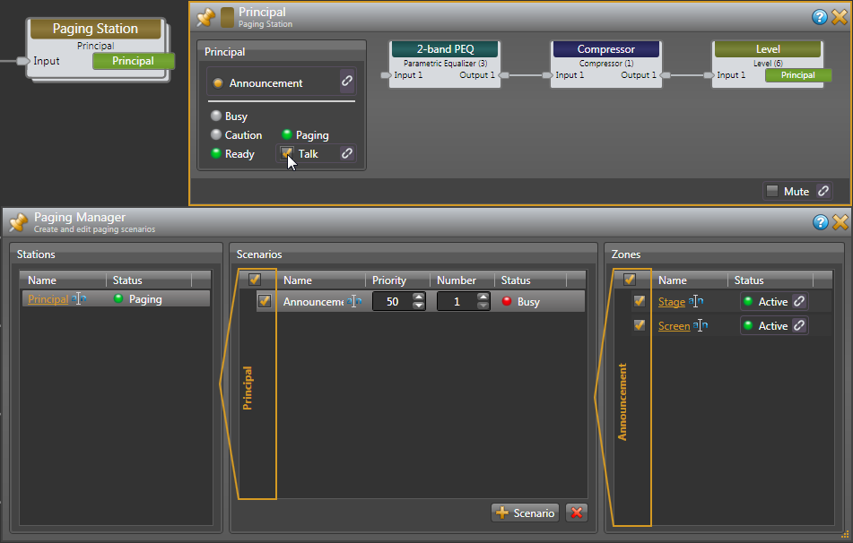
The Paging Manager is an easy and powerful way to set up multiple page sources and zones in different Scenarios. With more output zones, it’s easy to set up several combinations. This is really valuable for an entire school. For instance, if each classroom was a different zone, a single class or a group of classrooms are selectable inside a Scenario. Make a Scenario that includes the music and theater departments. Make another that includes the gym and playground. Tick all the Zones to create a Scenario to page everywhere. It’s easy to test by clicking on each of the Scenarios and watch how the Zone checkboxes change. You might consider installing a PAGER1for the Principle's office, a tabletop RAD with a mic jack that gives the end user a selection list of scenarios created here.
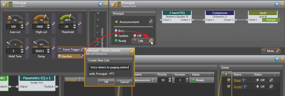
Now that paging is tested, let’s link Voice Detect activity to the Paging Station Talk button. After we link this, testing can only be done with an actual live audio signal. Open the Voice Detect block by double-clicking its title bar. There is no signal, so Voice Detect shows “Inactive.” When the system gets signal from the Principal this will go “Active” once the Threshold is exceeded.
To the right of the Inactive (Active) indicator in the Voice Detect dialog, hover over the unlinked icon ![]() until you see a floating gold link icon
until you see a floating gold link icon ![]() added to your mouse cursor. As you click this link and drag it to the Talk checkbox in the Paging Station, you’ll see the Talk area highlight in gold, leading your way to a compatible link. Release the mouse when you drag over the Talk link icon, and an Create New Link confirmation appears, prompting you to name the toggle link — call it Voice detect to paging station. Click OK, and both link icons activate by turning purple
added to your mouse cursor. As you click this link and drag it to the Talk checkbox in the Paging Station, you’ll see the Talk area highlight in gold, leading your way to a compatible link. Release the mouse when you drag over the Talk link icon, and an Create New Link confirmation appears, prompting you to name the toggle link — call it Voice detect to paging station. Click OK, and both link icons activate by turning purple ![]() .
.
We’re done with paging, so you can close these dialogs. Here’s another good place to save your work.
The Room Combine Processor simplifies the design of a room combine audio system by allowing you to think about one room at a time, without worrying about specific walls or previous configurations for other room combinations.
Double-click the Room Combine heading at the top of its block to open it. The first time you open this, a page of instructions appears, which I’ll cover here. This text disappears as soon as you drag a room into the workspace.
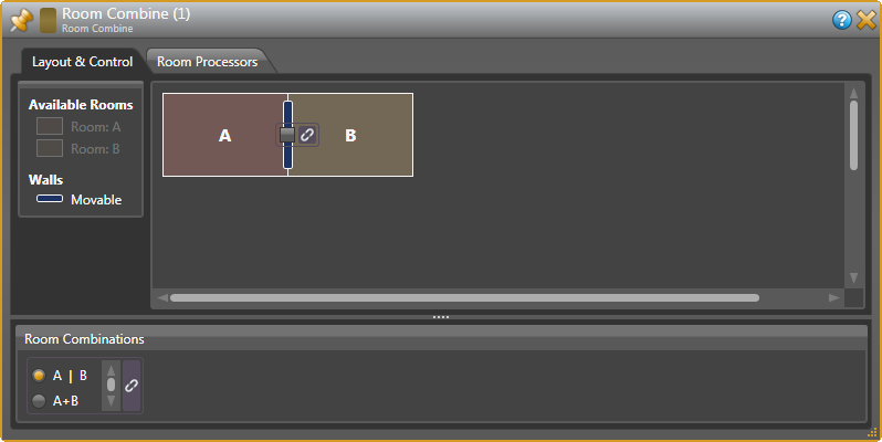
Under the Layout & Control tab, we have two Available Rooms. These are spaces created when all walls are closed. Drag Room: A anywhere on the left side of the workspace. Drag Room: B over so it snaps on the right side of Room A. Grab any side of the rooms and stretch them wide or deep to mimic your floor plan.
Drag a Movable Wall over so it snaps between Rooms A and B. At the bottom of this dialog, you’ll see the two possible room combinations: A | B, or A+B. When you add more rooms, the possible combinations are created for you here. Click on the gray checkbox in the center of a moveable wall, and see the Room Combinations change at the bottom. Pretty cool, right? Uncheck the box so the wall is closed for now.
The installation plans for a SPST switch to connect to a HAL3s Logic In port to tell HAL if the wall is open or closed. Some wall systems provide this contact closure switch. We can use a toggle light switch in a US electrical box labelled OPEN and CLOSED, mounted in the A/V cabinet by the screen. Note that once we link a wall to a control, we can’t make any more changes to the room and wall layout without removing the link.
At the left side of Halogen, open the Control tab. Click the little arrow left of Logic In to show all four available Toggle ports. We’ll use Toggle 1 for the Fire Alarm later, so let’s use Toggle 2 for the wall now. Click the rename icon ![]() to relabel Toggle (2) to Wall Open.
to relabel Toggle (2) to Wall Open.
Let’s make a link from the moveable wall in our room layout to the Wall Open Logic In toggle. Hover over the unlinked icon ![]() next to the moveable wall until you see a floating gold link icon
next to the moveable wall until you see a floating gold link icon ![]() added to your mouse cursor. As you click this link and drag it to Logic Inputs, you’ll see all the toggles highlight in gold. Release the mouse when you drag over the Wall Open link, and a Create New Link confirmation allows you to name the toggle link — call it Wall Open Toggle. Click OK, and both link icons turn purple
added to your mouse cursor. As you click this link and drag it to Logic Inputs, you’ll see all the toggles highlight in gold. Release the mouse when you drag over the Wall Open link, and a Create New Link confirmation allows you to name the toggle link — call it Wall Open Toggle. Click OK, and both link icons turn purple ![]() .
.
Test this by clicking on the orange Wall Open text in the Control tab. You’ll see a checked box next to Wall Open. While unchecking and checking this, watch the wall and the Room Combinations change as the wall opens and closes. The wall toggle switch now tells the room combine block the proper state.
Click the Room Processors tab in the Room Combine block. Check and uncheck the Wall Open switch, and notice the little green lightning circles ![]() in the lower right corner of the Room Processors. These tell you which of the three possible room states are active at any time: A with the wall closed, B with the wall closed, and A+B as one room when the wall is open. These alternate as you flip the Wall Open switch on and off.
in the lower right corner of the Room Processors. These tell you which of the three possible room states are active at any time: A with the wall closed, B with the wall closed, and A+B as one room when the wall is open. These alternate as you flip the Wall Open switch on and off.
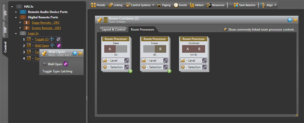
Name each possible room, right below each Room Processor heading: Stage, Screen, and Combined.
Here's what we want when the wall is open:
Here's what we want when the wall is closed:
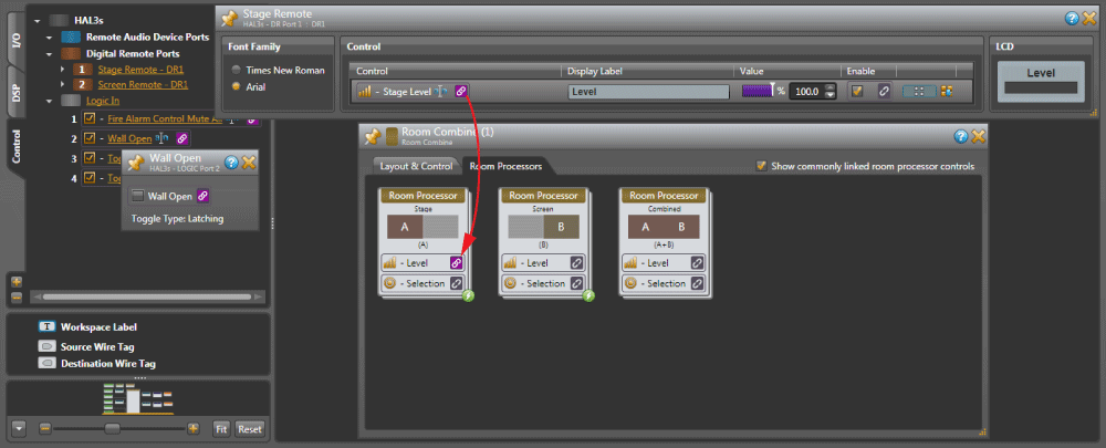
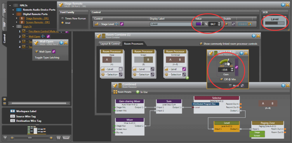
Let’s start with the Stage DR1 Remote. Click the Control tab at the left, and click on the orange underlined name of the Stage Remote – DR1. This opens the DR1 dialog. Change the name of the Control to Stage Level, and change the name of the Display Level to just Level.
Move the DR1 dialog out of the way so you can see the Room Combine block. Double-click the Room Combine header block to open its dialog, and click the Room Processors tab. Place the DR3 dialog and the Room Processors dialogs next to each other.
In the Control tab at the left, click the arrow by Logic In to see all four toggles. Click the Wall Open text to show the Wall Open checkbox. This lets us open and close the wall to activate the combinations of Room Processors.
Uncheck Wall Open to virtually close the wall. The green lightning circles at the lower right of Room Processor A and Room Processor B tell you these rooms are active. When the wall is closed, we only want the Stage Remote to control the level in the Stage Room Processor A.
Let’s make the link from the Stage Level Remote to the Room Processor Stage A Level. Hover over the unlinked icon ![]() next to the DR1 Stage Level control until you see the floating gold link
next to the DR1 Stage Level control until you see the floating gold link ![]() added to your mouse cursor. As you click this link and drag it to the Room Processors, you’ll see all the Levels highlight. Release the mouse when you drag over the Room Processor Stage Level link, and a Create New Link confirmation prompts you to name the link — call it Stage Level to Stage Room. Click OK, and both link icons activate by turning purple
added to your mouse cursor. As you click this link and drag it to the Room Processors, you’ll see all the Levels highlight. Release the mouse when you drag over the Room Processor Stage Level link, and a Create New Link confirmation prompts you to name the link — call it Stage Level to Stage Room. Click OK, and both link icons activate by turning purple ![]() .
.
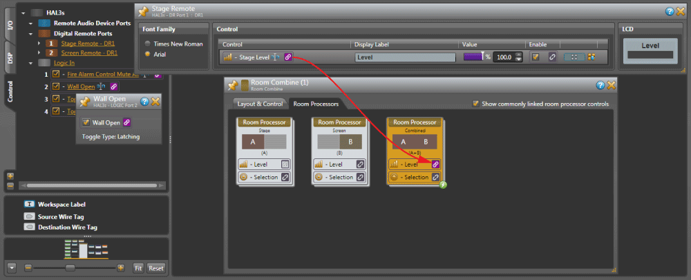
We’ll also want the Stage DR1 to control the level of the entire room when the wall is open. Check Wall Open to virtually open the wall. The green lightning circle is now at the lower right of Room Processor Combined A+B. Also notice the links we just made have turned light gray; inactive but still there.
Make the link from the Stage Level Remote to the Room Processor Combined A+B Level. Hover over the inactive link icon ![]() next to the DR1 Stage Level control until you see the floating gold link
next to the DR1 Stage Level control until you see the floating gold link ![]() added to your cursor. Release the mouse when you drag over the Room Processor Stage Level link, and an Add New Link box appears — call it Wall Open Level. Click OK, and both link icons activate by turning purple
added to your cursor. Release the mouse when you drag over the Room Processor Stage Level link, and an Add New Link box appears — call it Wall Open Level. Click OK, and both link icons activate by turning purple ![]() .
.
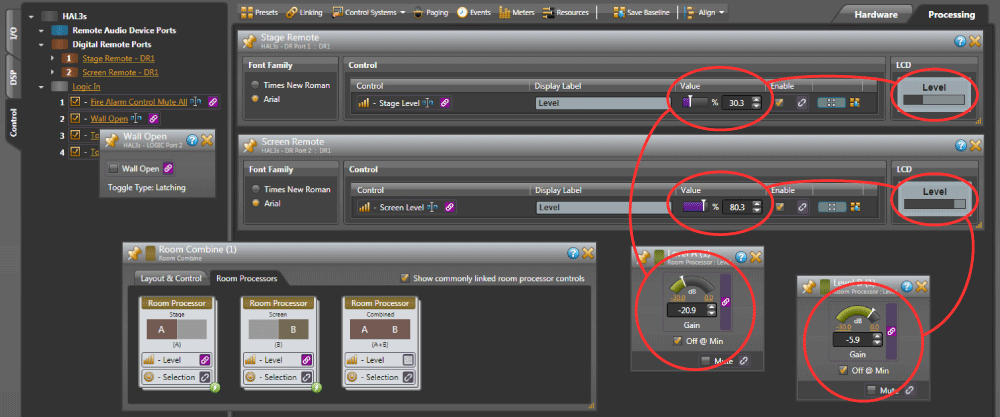
Let’s test the DR1 for successful Level links. With the wall still open, double-click on the Room Processor Combined A+B heading. Now you see the blocks and signal path inside the Room Processor. Double-click on the green header Level block inside here, and you’ll see this has an active link — this is what we linked to from the remote, we just didn’t have to open several boxes to get here. Test the level link by grabbing the white line of the green arc in the Level dialog, and move your mouse up and down. You’ll see the Control Value move, and you’ll see the DR1’s Value and LCD display bar move. This confirms it’s all linked and working.
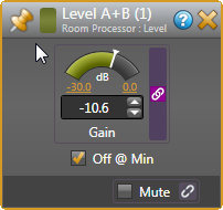 The DR remotes always display in percent, 0% for off, and 100% for full on — while the Level blocks display in dB. In the Level block, checking the Off @ Min box allows the DR1 to mute audio completely when turned fully counter-clockwise. If you don’t want it off at minimum, you can set the max and min volume by clicking the yellow underlined numbers at the ends of the green arc in the Level block.
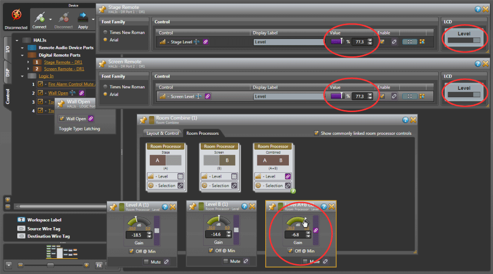
Test the Stage Level remote with the Wall Closed the same way. Close the virtual wall by unchecking the toggle. Open the Room Processor Stage A, then open the Level block inside of that. Grab the value of either the green bar in the Level block, or the purple bar in the Remote block, move it around, and both linked values change.
Now let’s set up the Screen Remote the same way. The difference will be in the names. To remind you, here are the steps in brief for linking the Screen Level control with the wall closed:
Here are the brief steps to link the Screen Level control with the wall open:
Test everything by opening all the Level dialogs that we just linked. This is how it should behave:
Now that we’ve just added to a link, you need to understand the bucket principle. When you link one source to one target, it doesn’t matter which direction you go. You can go from a control to a level, or a level to a control. But if you plan to link to more than one thing, like we did connecting both Remotes to the Combined A+B Room Processor, then you need to know where your bucket is. When you grab a link and drop it, you create a bucket at the destination, and you name the bucket. In this tutorial, I’ve had you drag from the DR1s to the Level blocks in the Room Processors, so the Level blocks are the buckets.
There are four types of links: Levels, Selects, Toggles, and Commands. As you drag an unlinked item, only similar compatible controls will highlight in gold. That is, only a Level control can link to a level block, and vice-versa. You can’t link a level control to a toggle. Only similar link types will highlight, so it’s easy to see where you can drag a link to.
Link Names can’t be repeated, and if you try, Halogen will auto-number them. Be descriptive so you can modify, remove, add, or find your buckets.
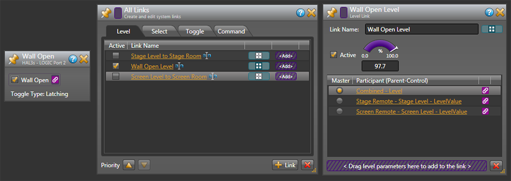
Click Linking on the Processing workspace toolbar. Here are all the links we’ve made so far, sorted by the tabs. See the three Level links to the two remotes, and the two Toggle links we made so far.
You’ll see checkboxes by the Active links. Checking and unchecking the Wall Open toggle changes the active state of each link. When the virtual Wall is Open, only the Wall Open Level link is Active. If the checkbox here is Active, it’s a purple link ![]() in the processing map. If the checkbox is Inactive (empty), it’s a light gray link
in the processing map. If the checkbox is Inactive (empty), it’s a light gray link ![]() in the processing map.
in the processing map.
Click on the orange Wall Open Level link to see its dialog. In the lower portion, the lit Master (on the left) is your current bucket, and the other lines are the sources to that bucket. If you forgot where you put your bucket, here’s where you can find it. You can see why good link names help, especially in larger systems.
Use All Links to clean up, delete or re-make a link. Delete a link by highlighting a row and clicking the red ![]() at the bottom. Any corresponding purple
at the bottom. Any corresponding purple ![]() links will become unlinked
links will become unlinked ![]() . This is helpful if you get confused, change your mind, or want to redo a link. You can edit the link names by clicking on a rename icon
. This is helpful if you get confused, change your mind, or want to redo a link. You can edit the link names by clicking on a rename icon ![]() .
.
Links have priority. A link at the top overrides any link below if they share the same block or control. Notice the Priority up and down arrows at the bottom of the All Links window. This lets you highlight a link and change its rank. We don’t need to change Priority here.
Now is a good time to make sure everything is working the way we want with the wall closed. Open up the dialogs for the Stage Remote, Screen Remote, Wall Open logic checkbox (unchecked, wall closed), Room Processor A Level and Room Processor B Levels and arrange so you can see them all at once. Grab any white value bar, move your mouse, and see the correct linked remote controls and Level blocks track each other. If you close the virtual wall, the levels match each other, and changing one DR1 value changes the other. If anything isn’t working, the All Links window is a good troubleshooting spot.
The remotes are done; save your good work.
Many Fire Departments and city codes have sound system requirements. Some want the inputs to mute but leave the system on for announcements. Some want the system muted entirely so an alarm is heard. Check your local requirements.
This city building code requires sound systems turn off so the alarm can be heard. Alarm systems usually provide a relay closure on a terminal block for the sound system. This school’s alarm system has a normally open relay closure that closes during an alarm. At installation time, attach a twisted-pair of wires to the HAL3s Logic In terminal 1 and ground.
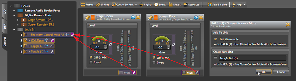
In the Control tab, click the arrow by Logic In to make all toggles visible. Name Toggle (1) as Fire Alarm Control Mute All.
Open both the orange Stage Output and the Screen Output blocks. Link direction matters, since we will have the two output blocks linked to one toggle control. The Fire Alarm Control Mute All toggle will be the bucket where both links meet.
Drag the unlinked Mute icon ![]() from the Stage Room Output as it gets a gold link
from the Stage Room Output as it gets a gold link ![]() cursor, and the Logic In toggles highlight in gold. Drag it to the Fire Alarm Control Mute and release the mouse over its unlinked icon
cursor, and the Logic In toggles highlight in gold. Drag it to the Fire Alarm Control Mute and release the mouse over its unlinked icon ![]() , name the link Fire alarm mute, click OK, and the icons turn purple
, name the link Fire alarm mute, click OK, and the icons turn purple ![]() .
.
Drag the unlinked Mute icon ![]() from the Screen Room Output as it gets a gold link
from the Screen Room Output as it gets a gold link ![]() cursor, and the Logic In toggles highlight in gold. Drag it to the Fire Alarm Control Mute and release the mouse over the already linked icon
cursor, and the Logic In toggles highlight in gold. Drag it to the Fire Alarm Control Mute and release the mouse over the already linked icon ![]() . Release the mouse and you’ll get an Add to Link dialog; click OK.
. Release the mouse and you’ll get an Add to Link dialog; click OK.
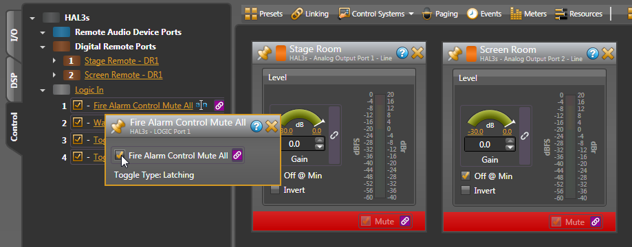
You can test this by clicking on the left column Logic In Fire Alarm Control Mute All text to get its dialog. Click the checkbox here, and notice both orange output blocks get red across the bottom Mute area. The top toolbar also indicates a Mute in red, alerting you in case your blocks aren’t visible. The orange processing blocks in your map also get a red line.
The Fire Department requirement may instead require you to mute the room inputs, yet leave the system on for emergency announcements. Instead of creating links to mute the two orange Output blocks, create links to mute the three Level blocks in all three possible rooms of the Room Combine block. Paging is still possible because the Paging Zone is after the Level control. Do this in the Room Combine by opening the Room Processors tab, opening each Room Processor, opening each Level block, and linking their Mutes to the Fire Alarm Control Mute All toggle.
The Fire Alarm is done. The Fire Department saves lives and property, so here’s a hint to save your work.
Any computer, tablet, or smartphone on the premises will have a web browser. Any web browser that has access to the local network on Wi-Fi can talk to HAL, if the HAL is on the same Wi-Fi network. Web Controls are another way of remote-controlling the system, with no additional remote to buy, so no added expense. Using drag-and-drop layout and links makes creating web controls for a HAL system is easier than you imagine. Give web controls to the faculty for more controls without buying more remotes. In this system, we have DR1 Remotes controlling the volume in each room. Most of the time this is enough, but they may have an event that requires controlling individual levels; web controls can do it!
Above the Processing Map, click the Control Systems drop-down, and choose Control Page Designer. Web browsers come in all sizes and resolutions, so the first question to ask is: on what device will these controls be used? In the lower left, click the Outline menu to see popular phones and tablets. Don’t see your device? Click the daisy to the right of the menu, and you have an expandable window that lets you check the devices to display in the Outline menu. The icon before the daisy lets you choose portrait or landscape. If you have more than a few controls, choose Landscape. If you’re designing for a desktop monitor, choose None as the outline.
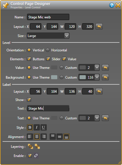
Let’s set up a web page for the principal (or A/V specialist) that includes the five source levels, so a tablet can control the volume of any single source anywhere in the room. I heard the school has an Apple iPad, so I’ll select that. You’ll see a dashed line as your boundary to work within. Since we are only making five sliders, make the Default Control Size: Large.
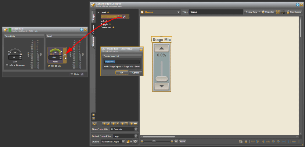
Open the Controls tab at the left. Add a new Level by clicking the “+” sign to the right of it, or click the ![]() icon at the bottom. Click the rename icon
icon at the bottom. Click the rename icon ![]() to name this Stage Mic. Before you close this rename window, press Ctrl-A (select all) and then Ctrl-C to copy this name on your clipboard; it will save you retyping the same name.
to name this Stage Mic. Before you close this rename window, press Ctrl-A (select all) and then Ctrl-C to copy this name on your clipboard; it will save you retyping the same name.
Drag this Stage Mic Level onto the left side of the screen. Let go, and notice you can reposition it and its title around. Double-click on the Level (1) title and you’ll get a properties toolbox of size, color and style options for the Label. For now, highlight the Level (1) text in the Label Text field and press Ctrl-V to paste Stage Mic from your clipboard. Close this toolbox.
Open the green-headed Stage Mic Input block. Drag the unlinked Stage Mic ![]() Level icon in the Control Page Designer as it gets a gold link
Level icon in the Control Page Designer as it gets a gold link ![]() cursor, and the Input Level highlights in gold. Drag it to the Stage Mic Level and release the mouse over its unlinked icon
cursor, and the Input Level highlights in gold. Drag it to the Stage Mic Level and release the mouse over its unlinked icon ![]() . Put your cursor in the Create New Link dialog, press Ctrl-A and then Ctrl-V to paste Stage Mic as the link name. Click OK, and both link icons turn purple
. Put your cursor in the Create New Link dialog, press Ctrl-A and then Ctrl-V to paste Stage Mic as the link name. Click OK, and both link icons turn purple ![]() .
.
Let’s do the same for the rest of the level controls:
Repeat until the Stage Mic, Stage Aux, Screen Mic, Screen Aux, and Blu-ray all have linked level controls. When you Ctrl-V (paste) the name into the Properties Label Text, it might not appear correctly in the Designer. This is probably because Label container is too small. Simply grab an edge of the title and pull it over to make the container larger, and then you’ll see your label pop in. Or get pixel-precise in the Properties.
You can grab, stretch, move the fader and label any way you like visually, or you can get pixel-precise by entering XYWH numbers for each element. Every element has properties to tweak for a nice-looking layout. You can shift-click or click drag around multiple elements and use the align tools across the bottom of the Design window. Sliders are easier to adjust with fingers when they are longer. On small screens such as phones, removing the slider completely, displaying only up and down buttons, is easier for some users.
Right-click on an empty area, select Properties, and try different overall Themes for your page. Choose a custom color background to match your décor. Click the Elements tab on the left to add more labels, lines or import the school mascot logo.
Now let’s test. In Control Page Designer, Click the Preview Page button, and the page launches in your computer’s default browser. Open any or all of the Input blocks in your Processing Map. Resize your browser window so you can see it next to all the open dialogs. Operate any control on your browser screen. See how the matching Levels change? Pretty cool, and easy to set up.
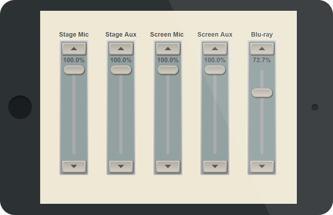
This is just a sample of web controls you can make. For example, link sliders to individual Parametric band Gains for room bass, mid and treble controls. Add the Threshold control for the Principal’s Voice Detect. Web controls are a powerful feature that faculty will love, created without programming knowledge or extra hardware expense. Below is the finished simple iPad design for this school.
Let’s inspect each block and its available controls. Properties are opened by double-clicking any block’s title bar. Let’s go left to right, from the input to output.
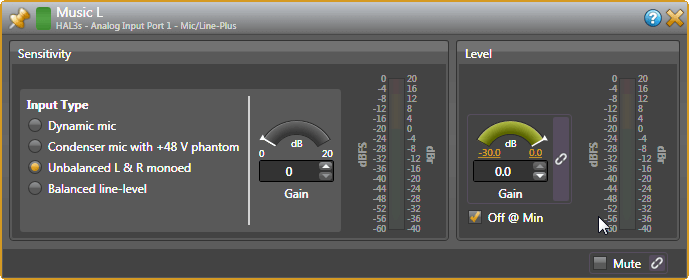
Input Blocks: When using unbalanced (RCA or 3.5 mm) sources, set the analog Mic/Line-Plus inputs to Unbalanced L&R monoed, (even if connecting one channel). Keep unbalanced lines short, less than 10 feet (3 meters). Use balanced line-level inputs if your source has them, and select Balanced line-level. Adjust the Level Gain during installation.
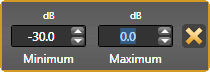 All the Gain Levels in Halogen are unique because the range of the Gain is adjustable. Click on the gold numbers at either end of the green arc. This lets you set a max and min range if the end users are better off with less control. The defaults of -30 dB minimum and 0 dB maximum, along with the Off @ Min checkbox, behave like a regular off-to-on volume control.
The input block will vary depending if it is one of the green inputs on the back of the HAL, or an input coming from a RAD. The RAD16z, RAD26 and HAL3s inputs are Mic / Line / Line-Plus, with the type chosen here in the input block. The Line-Plus allows unbalanced stereo sources to be wired left-ground-right on a balanced 3-terminal connector, and then mono’ed to a single input.
RADs with XLR jacks have a Euroblock connector on the back. This allows external connectors, like the stage floor pocket XLR in this school to be wired to the mic input on the RAD.
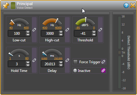
Voice Detect Block: This turns the Paging Station block on from the Principal’s office without running a separate push-to-talk wire down the hall. Most parameters will need to be set after installation using the Principal’s mic.
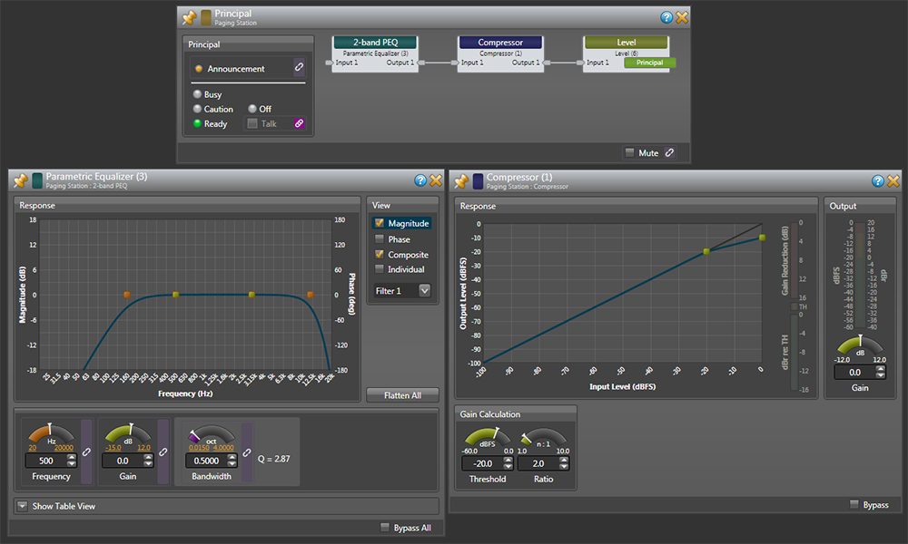
Paging Station Block: This is triggered by the Voice Detect block in this system, which then sends paging signals to the Paging Manager which forwards to the Room Combine block. It contains status indicators for testing, EQ, compression and a Level.
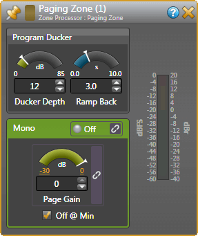 Room Combine Block: We’ve gone through this block before, but there’s an inner block you’ll want to adjust during installation. Open a Room Processor, and you’ll see a Paging Zone block at the end of the chain. This is where the output of the Paging Station mixes in. There will be a different Paging Zone for each Room Processor.
Open the Paging Zone dialog. Ducker Depth lowers the local program music temporarily during a page. The default is 12 dB and a good starting place. The Ramp Back time is the seconds it takes, after paging, for music to return to its regular volume. The 3-second default is fine. If the Page volume is too high in a zone, lower the Paging Zone Page Gain. This installation has three possible rooms, so make adjustments to each room. Once you have one room’s settings correct, you could copy and paste settings to the next room’s paging zone using the Ctrl-C and Ctrl-V method.
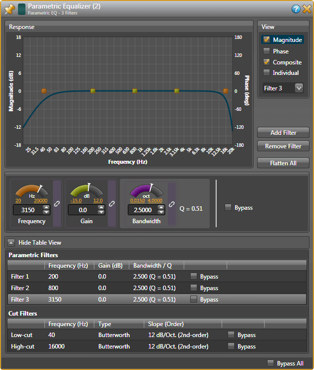
Parametric EQ Blocks: Treat these like 3-band tone controls (Low, Mid, & High). It’s easiest to see all settings at once by clicking the Show Table View option. To change a value, move the arc indicator, click the up/down value arrows, or highlight the numbers and type directly. Here are some suggested starting settings.
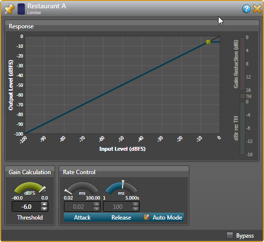
Limiter Blocks: These help prevent amplifier clipping and protect loudspeaker drivers. The Threshold defaults at -6 dB with a checked Auto Mode to take care of Attack and Release times. Set this block with live audio during installation. Don’t limit audio constantly or it will sound bad and could overload and overheat the speakers. Read the Dynamics Processors RaneNote www.rane.com/note155.html to understand how Limiters work.
Output Blocks: These are the final stage that set the volume at the orange blocks that connect to your amplifier inputs. An Output block looks like and has the same functions as a Level block. Rane always recommends balanced wiring if it is available (positive, negative and ground wires) to reduce hum and noise. If the amplifier only has unbalanced connectors (like RCA inputs), then use the + and ground terminals on the HAL3s outputs. Locate the amplifier nearby and keep unbalanced cables short (under 10 feet [3 meters]).
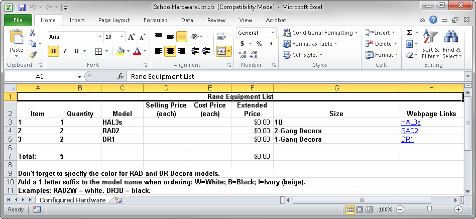
If you’ve finished the design, Halogen can generate your Rane shopping list. Click the Hardware tab, and Generate List in the toolbar at the top. It will generate a spreadsheet showing quantities, models, price columns, and links to online product details. Copy and paste this into another spreadsheet, or use this as the starting point for the other equipment in your proposal.
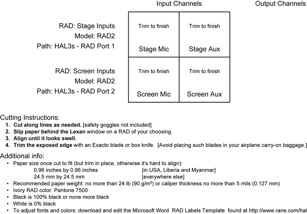
Halogen can help make your RAD installations look professional by making labels for you. You already entered the names of the inputs early in your design. In the Hardware Workspace, click the Generate Labels button at the top. Choose the same color that you chose your RADs. Click Create, and then View, and your PDF viewer opens for you to print. Cut out the labels and insert them behind the little windows at the top of each RAD. After the label is in, trim the top edge with an Exacto blade for the cleanest look. Printing and installing labels before going to your job site really helps when you have lots of RADs.
Rane hopes this tutorial makes Halogen easier than you thought it would be. If you get stuck, or don’t understand a control, use Halogen’s built-in Help system by clicking on the blue-circled question mark ![]() at the top of any block. If you have a system you need help with, our HAL specialists at the Rane Factory in Mukilteo, Washington are ready to help by email or phone. Call 425-355-6000, Monday through Friday, 8:30 am to 5 pm Pacific Time.
at the top of any block. If you have a system you need help with, our HAL specialists at the Rane Factory in Mukilteo, Washington are ready to help by email or phone. Call 425-355-6000, Monday through Friday, 8:30 am to 5 pm Pacific Time.