The DR (digital remote) models are designed to control the HAL series of multiprocessors in various ways: volume setting, preset recall, source selection, or reset / toggle system states. The DR1, DR2, DR3 and DR6 allow customizing labels for end users, while the DR4 and DR5 offer incorporating custom switches and other devices to control HAL. Status indicators on each HAL or EXP host, and in Halogen software, report wiring status to assist troubleshooting. All are hot-swappable with homerun connections using shielded CAT 5e (or better) cable. DRs get their control functions from the HAL port they are connected to, which eliminates individual addressing. DRs connect to either a DR port (brown) or a RAD port (blue) on the rear of a HAL or EXP.
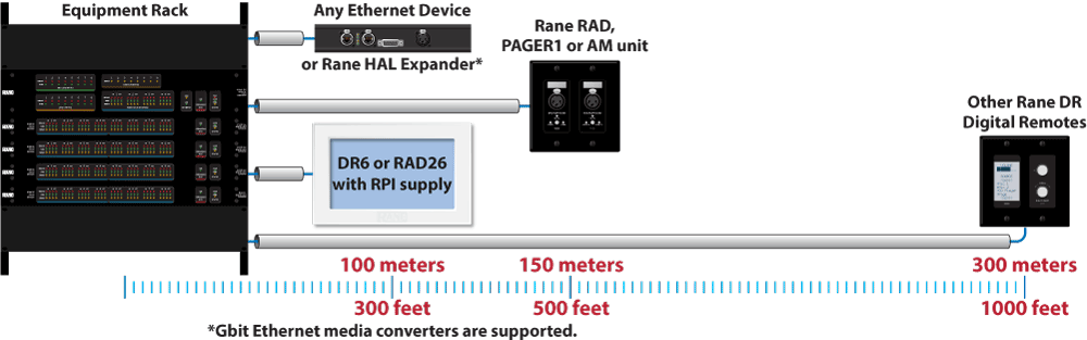
While the RADs have a 150 meter (500 foot) maximum distance, any DR (except the DR6) can run up to 300 meters (1,000 feet) away from its HAL. It's possible to increase distance by connecting a DR to a EXP1x, EXP3x, or EXP5x Expander, which is another 100 meters (300 feet) from a HAL1x, thereby increasing to 400 meter (1,300 feet) maximum distance from the HAL1x to the DR. Greater distances can be accomplished using Expanders with Gbit Ethernet media converters and fiber optic cable.
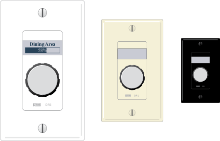
The Rane DR1 is a Level Control remote with several features that make it stand out against any other wired remote. The LCD display shows the name of the Zone or Group that it is connected to, customizable in Halogen Software to anything you like. The Level value is also shown, and updated dynamically when it is changed elsewhere, such as in a linked group with multiple Remotes connected. Display screens are dynamic, automatically updating when the available options change through preset activation, room combining, and so on. Therefore, the user always sees the options that are currently available. The display has a backlight for readability that turns on when used, then dims after a short time period.
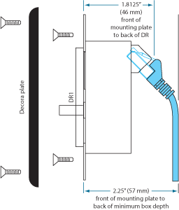
The DR1 fits in a standard U.S. electrical box and comes with a matching Decora plate cover.
To mount Rane DR1s in a rack, we recommend Lowell rack panels. Note: Lowell's 8-wide panel accepts only single gang devices and does not accept two-gang devices such as Rane RADs or DR2 or DR3. Use Lowell's 9-wide model which accepts multi-gang Decora products.
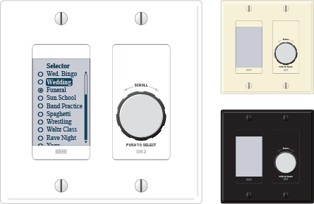
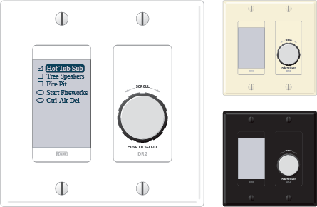
The DR2 offers both Single Selector and List of Toggles/Commands behaviors. The LCD display has a backlight for readability that turns on when used, then dims after a short time period. The selection names are customizable in Halogen Software to anything you like.
Display screens are dynamic, automatically updating when the available options change through preset activation, room combining, and so on. Therefore, the user always sees the options that are currently available. You can configure a DR2 to behave in one of two ways:
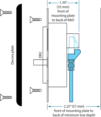
The DR2 fits in a standard double-wide U.S. electrical box and comes with a matching Decora plate cover.
Home run shielded CAT 5e connections to the HAL or EXP (up to 300 meters [1000 feet] away) eliminate addressing, external power, and the need to test the cables.
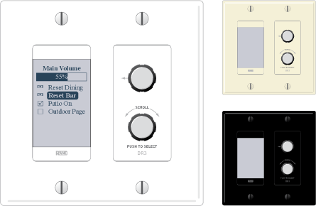
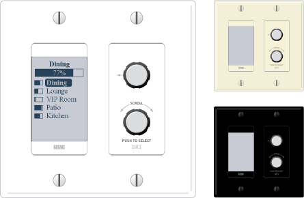
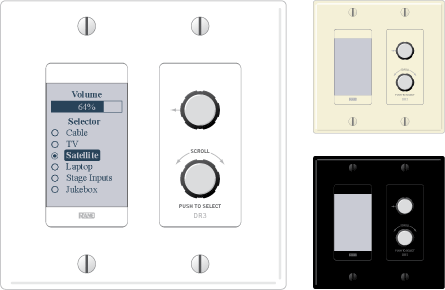
The three DR3 behaviors are Single Level & List of Toggles/Commands, List of Levels for either multizone volume control or input source mixing, and Single Level plus Selector. The LCD display has a backlight for readability that turns on when used, then dims after a short time period. The names are customizable in Halogen Software to anything you like.
The DR3 is extremely flexible, as it can control both selection and volume. You can think of the DR3 as two different remotes—a selector and a level. One knob makes a selection, the other knob changes the volume. Display screens are dynamic, automatically updating when the available options change through preset activation, room combining, and so on. Therefore, the user always sees the options that are currently available.
Halogen software lets you configure a DR3 in one of three ways:
The DR3 fits in a standard double-wide U.S. electrical box and comes with a matching Decora plate cover.
Home run shielded CAT 5e connections to the HAL or EXP (up to 300 meters [1000 feet] away) eliminate addressing, external power, and the need to test the cables.

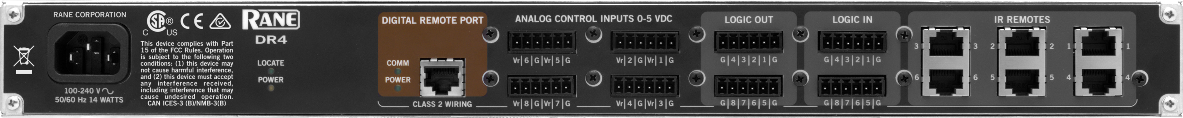
The DR4 Digital Remote adds additional logic input and output ports to any HAL, enabling simple analog level and logic I/O controls plus IR2 remotes for wall sensing, enabling automatic sound routing when moveable walls open and close. The DR4 offers eight logic ins and outs, six IR2 ports and eight analog control input ports for pot-on-a-wall level control. Multiple DR4's can connect to Digital Remote Ports on any HAL, up to 300 meters (1000 feet) away.
 These inputs on the DR4 are similar to the Logic In ports on a HAL. You can configure each of the eight input ports in one of three ways: toggle, command, or selector.
The Toggle configuration allows a Toggle command with an on/off switch. You can configure each port type to be either Momentary or Latching.
 The Command configuration allows triggering a Command control from an on/off switch, which can link to one or more Command controls such as a Command preset or a linkable button in a processing block property dialog.
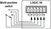
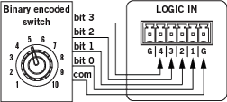 The Selector configuration uses either a multi-position switch or a binary switch. You can connect a physical device to any or all of the Logic In ports and configure the ports in Halogen so that they make the desired selection according to the state of the physical device. Wiring details are in the Halogen Software Help.
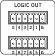 You can configure each of the 8 output ports in one of 2 ways:
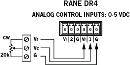 Each port allows an analog voltage source to control the value of a Level control in the Halogen Control palette. The input range for the port is from 0 V to 5 V, where 0 V corresponds to 0% on the associated Level control and 5 V corresponds to 100%.
Connect a physical 20k ohm linear-taper potentiometer; the Vc wiper provides the control voltage to the DR4. As you adjust the pot the voltage changes, which in turn changes any linked Level control in Halogen.
Each port allows an analog voltage source to control the value of a Level control in the Halogen Control palette. The input range for the port is from 0 V to 5 V, where 0 V corresponds to 0% on the associated Level control and 5 V corresponds to 100%.
Connect a physical 20k ohm linear-taper potentiometer; the Vc wiper provides the control voltage to the DR4. As you adjust the pot the voltage changes, which in turn changes any linked Level control in Halogen.
The IR ports are ideal for linking to the wall toggle controls in a Room Combine block, allowing automatic room configuration changes to occur as moveable walls change positions in a physical room. These ports are read-only, intended for the Rane IR2 (see its data sheet). When the IR Remote is sensing infrared the wall is considered ‘open’ and the associated toggle control in the Hardware Controls palette is checked.
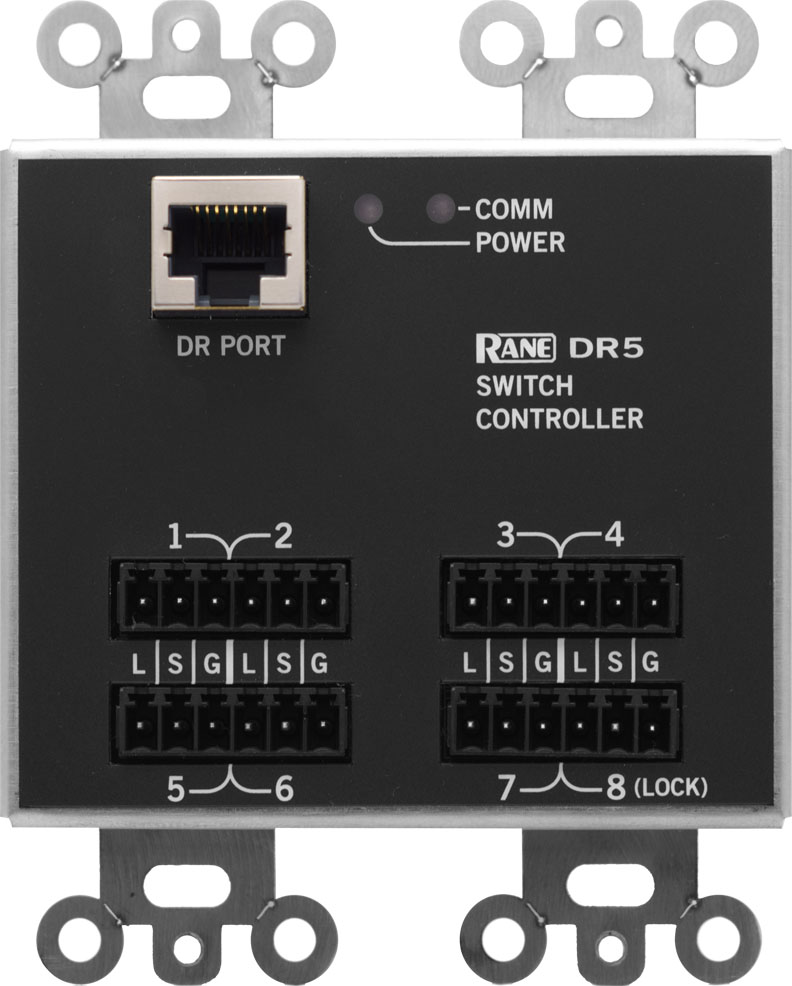
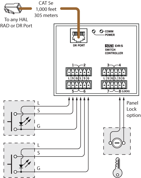
The DR5 Digital Remote offers additional logic input and output ports, enabling the use of simple analog switch controls in any HAL system. Lighted switch panels for room combine applications are easily integrated using the eight switch inputs and eight LEDs outputs on the DR5. Unlike the HAL and DR4 Logic I/O, the DR5 Logic Out is intended to drive the LED indicator on a room combine panel, and is a writable parameter. The DR5 is designed to fit in a standard US dual-gang electrical box, or mount directly near a room combine panel, up to 300 meters (1000 feet) away from a HAL or EXP.
These inputs on the DR5 are similar to the HAL’s Logic In ports. You can configure each of the 8 input ports in one of 2 ways:
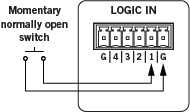
When nothing is connected to a Switch Input port, the hardware internally pulls the port to logic high (5 V). To trigger the command, a hardware device connected to the Switch Input port must pull the port voltage lower than the logic low threshold. One way to do this is to connect a physical normally open momentary push button switch to the port. When the end user pushes the button, the switch contacts close, pulling the Switch Input port low, which causes the Command to trigger. When the user releases the button, the port signal returns high and the port is ready for the next command.
In addition, you can configure port 8 to serve as a ‘lock’ input, allowing the user to selectively enable or disable all seven input ports with a physical switch attached between Switch Input port 8 and ground (G). When configured as a lock, the DR5 disables Switch Input ports 1 - 7 when the switch is closed and enables the ports when the switch open.
Note: To use the lock port, you must configure Switch Input 8 as a Toggle type of input. Once you have enabled the ‘lock’ port, you cannot move Switch Input port 8 or change its type to Command.
The DR5 provides eight LED output ports that are coupled to the state of the corresponding DR5 switch input controls. You can connect an LED to each port to have a visual indicator of the DR5 operations. The operation of an LED Output port is governed by the Switch Input port configuration:
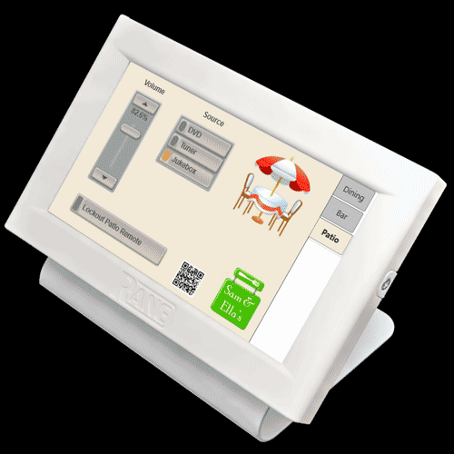
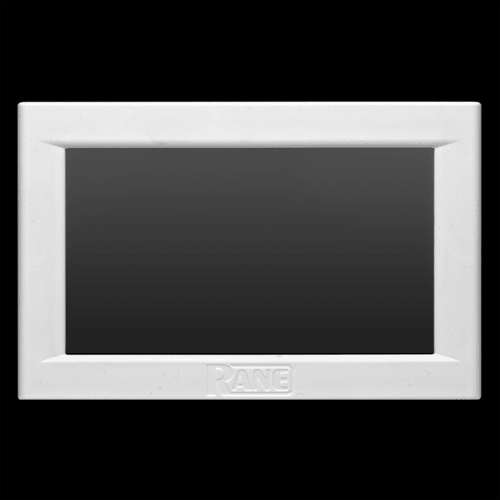
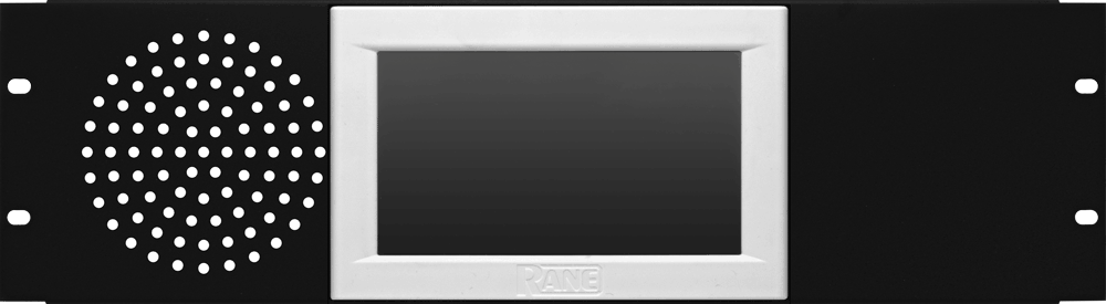
The DR6 is a fully customizable touchscreen remote for the HAL family. It supports multiple pages or tabs and any set of levels, toggles, selectors and/or commands. Drag, drop and resize controls any way that’s desired. Use custom background images and logos in full-color on the 7-inch LCD display.
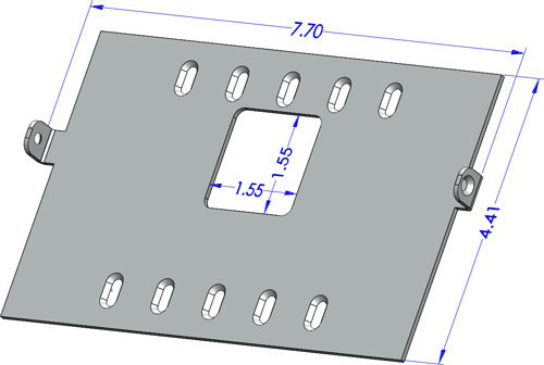
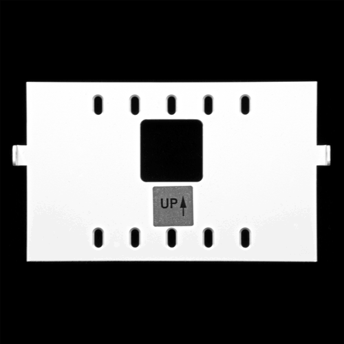
Screw the included wall-mount bracket over U.S. or international electrical boxes, or flush mount the 3/4" thick DR6 with a 2-inch (5 cm) square hole in the wall to accommodate the cable.
The included midspan power injector (not PoE) connects shielded CAT 5e (or better) cables between any HAL and the DR6 to deliver communications and the extra power needed for the display.
Optional, on-screen User Access logins secure management pages from public or staff use, and a programmable ambient light sensor automatically dims the backlight.
The Control Page Designer in Halogen 5.0 allows you to create one set of pages and use them in a web control design, DR6 display or both.
Dimensions from wall surface (cm): 12.5 h x 19.5 w x 2.5 d
Dimensions from wall surface (inches): 5 h x 7.7 w x .76 d
Weight: 166 g / 5.9 oz
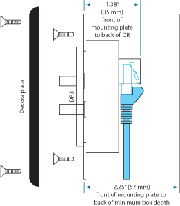
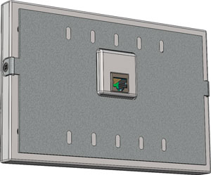
This assembled rear view shows the CAT 5 cable connection.

The RB2 was designed with the EIA 4? loudspeaker “standard” in mind, with a mounting bolt circle diameter of 120 mm, or 4.7? ±0.05?. Here are a few mechanically compatible speakers, according to their data sheets.
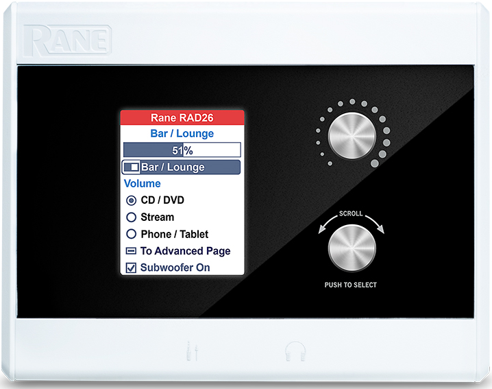
The new RAD26 starts with the functions of a DR3, but adds color to the LCD, adds audio in and out, adds logic in and out, adds a small stereo amplifier, adds a 3.5 mm input, adds a 3.5 mm headphone output, and more control options in Halogen. See all the details here.