This note, originally written in 1985, continues to be one of our most useful references. It's popularity stems from the continual and perpetual difficulty of hooking up audio equipment without suffering through all sorts of bizarre noises, hums, buzzes, whistles, etc.-- not to mention the extreme financial, physical and psychological price. As technology progresses it is inevitable that electronic equipment and its wiring should be subject to constant improvement. Many things have improved in the audio industry since 1985, but unfortunately wiring isn't one of them. However, finally the Audio Engineering Society (AES) has issued a standards document for interconnection of pro audio equipment. It is AES48, titled "AES48-2005: AES standard on interconnections -- Grounding and EMC practices -- Shields of connectors in audio equipment containing active circuitry."
Rane's policy is to accommodate rather than dictate. However, this document contains suggestions for external wiring changes that should ideally only be implemented by trained technical personnel. Safety regulations require that all original grounding means provided from the factory be left intact for safe operation. No guarantee of responsibility for incidental or consequential damages can be provided. (In other words, don't modify cables, or try your own version of grounding unless you really understand exactly what type of output and input you have to connect.)
Almost all cases of noise can be traced directly to ground loops, grounding or lack thereof. It is important to understand the mechanism that causes grounding noise in order to effectively eliminate it. Each component of a sound system produces its own ground internally. This ground is usually called the audio signal ground. Connecting devices together with the interconnecting cables can tie the signal grounds of the two units together in one place through the conductors in the cable. Ground loops occur when the grounds of the two units are also tied together in another place: via the third wire in the line cord, by tying the metal chassis together through the rack rails, etc. These situations create a circuit through which current may flow in a closed "loop" from one unit's ground out to a second unit and back to the first. It is not simply the presence of this current that creates the hum -- it is when this current flows through a unit's audio signal ground that creates the hum. In fact, even without a ground loop, a little noise current always flows through every interconnecting cable (i.e., it is impossible to eliminate these currents entirely). The mere presence of this ground loop current is no cause for alarm if your system uses properly implemented and completely balanced interconnects, which are excellent at rejecting ground loop and other noise currents. Balanced interconnect was developed to be immune to these noise currents, which can never be entirely eliminated. What makes a ground loop current annoying is when the audio signal is affected. Unfortunately, many manufacturers of balanced audio equipment design the internal grounding system improperly, thus creating balanced equipment that is not immune to the cabling's noise currents. This is one reason for the bad reputation sometimes given to balanced interconnect.
A second reason for balanced interconnect's bad reputation comes from those who think connecting unbalanced equipment into "superior" balanced equipment should improve things. Sorry. Balanced interconnect is not compatible with unbalanced. The small physical nature and short cable runs of completely unbalanced systems (home audio) also contain these ground loop noise currents. However, the currents in unbalanced systems never get large enough to affect the audio to the point where it is a nuisance. Mixing balanced and unbalanced equipment, however, is an entirely different story, since balanced and unbalanced interconnect are truly not compatible. The rest of this note shows several recommended implementations for all of these interconnection schemes.
The potential or voltage which pushes these noise currents through the circuit is developed between the independent grounds of the two or more units in the system. The impedance of this circuit is low, and even though the voltage is low, the current is high, thanks to Mr. Ohm, without whose help we wouldn't have these problems. It would take a very high resolution ohm meter to measure the impedance of the steel chassis or the rack rails. We're talking thousandths of an ohm. So trying to measure this stuff won't necessarily help you. We just thought we'd warn you.
The method specified by AES48 is to use balanced lines and tie the cable shield to the metal chassis (right where it enters the chassis) at both ends of the cable.
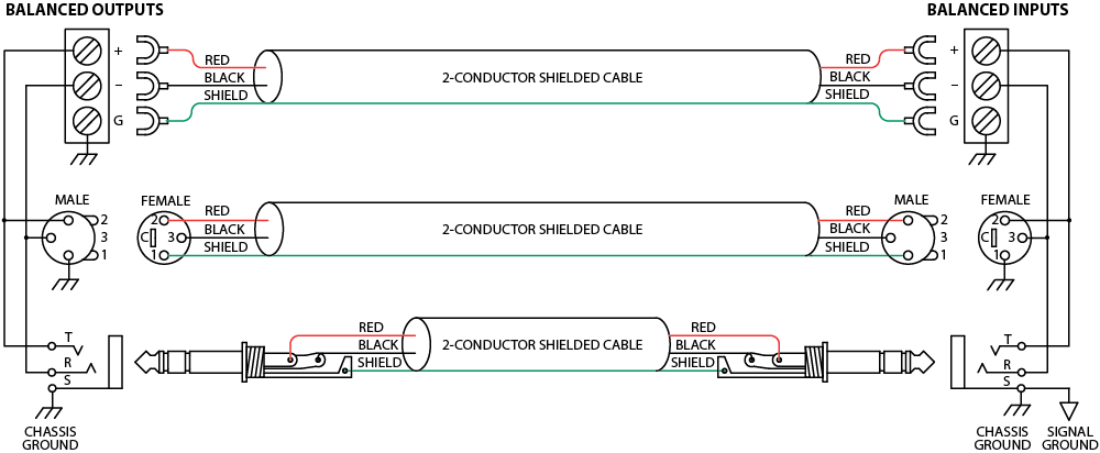
A balanced line requires three separate conductors, two of which are signal (+ and -) and one shield (see Figure 1a). The shield serves to guard the sensitive audio lines from interference. Only by using balanced line interconnects can you guarantee (yes, guarantee) hum-free results. Always use twisted pair cable. Chassis tying the shield at each end also guarantees the best possible protection from RFI [radio frequency interference] and other noises [neon signs, lighting dimmers].
Neil Muncy, an electroacoustic consultant and seasoned veteran of years of successful system design, chairs the AES Standards Committee (SC-05-05) working on this subject. He tirelessly tours the world giving seminars and dispensing information on how to successfully hook-up pro audio equipment2. He makes the simple point that it is absurd that you cannot go out and buy pro audio equipment from several different manufacturers, buy standard off-the-shelf cable assemblies, come home, hook it all up and have it work hum and noise free. Plug and play. Sadly, almost never is this the case, despite the science and rules of noise-free interconnect known and documented for over 60 years (see References for complete information).
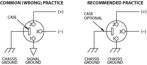
It all boils down to using balanced lines, only balanced lines, and nothing but balanced lines. This is why they were developed. Further, that you tie the shield to the chassis, at the point it enters the chassis, and at both ends of the cable (more on `both ends' later).
Since standard XLR cables come with their shields tied to pin 1 at each end (the shells are not tied, nor need be), this means equipment using 3-pin, XLR-type connectors must tie pin 1 to the chassis (usually called chassis ground) -- not the audio signal ground as is most common.
Not using signal ground is the most radical departure from common pro-audio practice. Not that there is any argument about its validity. There isn't. This is the right way to do it. So why doesn't audio equipment come wired this way? Well, some does, and since 1993, more of it does. That's when Rane started manufacturing some of its products with balanced inputs and outputs tying pin 1 to chassis. So why doesn't everyone do it this way? Because life is messy, some things are hard to change, and there will always be equipment in use that was made before proper grounding practices were in effect.
Unbalanced equipment is another problem: it is everwhere, easily available and inexpensive. All those RCA and 1/4" TS (Tip-Sleeve) connectors found on consumer equipment; effect-loops and insert-points on consoles; signal processing boxes; semi-pro digital and analog tape recorders; computer cards; mixing consoles; et cetera.
The rest of this note gives tips on how to successfully address hooking up unbalanced equipment. Unbalanced equipment when "blindly" connected with fully balanced units starts a pattern of hum and undesirable operation, requiring extra measures to correct the situation.
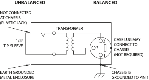
The quickest, quietest and most foolproof method to connect balanced and unbalanced is to transformer isolate all unbalanced connections. See Figure 2.
Many manufacturers provide several tools for this task, including Rane (see the BB22, BB44 and LT22). Consult your audio dealer to explore the options available.
The goal of these adapters is to allow the use of standard cables. With these transformer isolation boxes, modification of cable assemblies is unnecessary. Virtually any two pieces of audio equipment can be successfully interfaced without risk of unwanted hum and noise.
Another way to create the necessary isolation is to use a direct box. Originally named for its use to convert the high impedance, high level output of an electric guitar to the low impedance, low level input of a recording console, it allowed the player to plug "directly" into the console. Now this term is commonly used to describe any box used to convert unbalanced lines to balanced lines.
If transformer isolation is not an option, special cable assemblies are a last resort. The key here is to prevent the shield currents from flowing into a unit whose grounding scheme creates ground loops (hum) in the audio path (i.e., most audio equipment).
It is true that connecting both ends of the shield is theoretically the best way to interconnect equipment -- though this assumes the interconnected equipment is internally grounded properly. Since most equipment is not internally grounded properly, connecting both ends of the shield is not often practiced, since doing so usually creates noisy interconnections.
A common solution to these noisy hum and buzz problems involves disconnecting one end of the shield, even though one can not buy off-the-shelf cables with the shield disconnected at one end. The best end to disconnect is the receiving end. If one end of the shield is disconnected, the noisy hum current stops flowing and away goes the hum -- but only at low frequencies. A ground-sending-end-only shield connection minimizes the possibility of high frequency (radio) interference since it prevents the shield from acting as an antenna to the next input. Many reduce this potential RF interference by providing an RF path through a small capacitor (0.1 or 0.01 microfarad ceramic disc) connected from the lifted end of the shield to the chassis. (This is referred to as the "hybrid shield termination" where the sending end is bonded to the chassis and the receiving end is capacitively coupled. See Neutrik's EMC-XLR for example.) The fact that many modern day installers still follow this one-end-only rule with consistent success indicates this and other acceptable solutions to RF issues exist, though the increasing use of digital and wireless technology greatly increases the possibility of future RF problems.
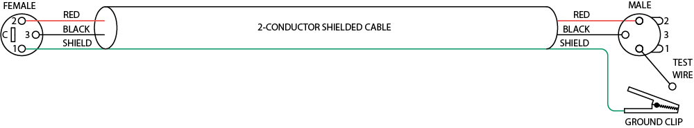
If you've truly isolated your hum problem to a specific unit, chances are, even though the documentation indicates proper chassis grounded shields, the suspect unit is not internally grounded properly. Here is where special test cable assemblies, shown in Figure 3, really come in handy. These assemblies allow you to connect the shield to chassis ground at the point of entry, or to pin 1, or to lift one end of the shield. The task becomes more difficult when the unit you've isolated has multiple inputs and outputs. On a suspect unit with multiple cables, try various configurations on each connection to find out if special cable assemblies are needed at more than one point.
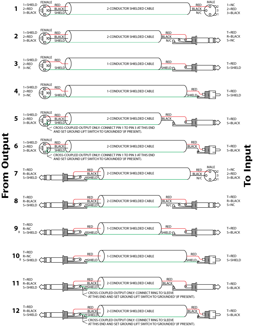
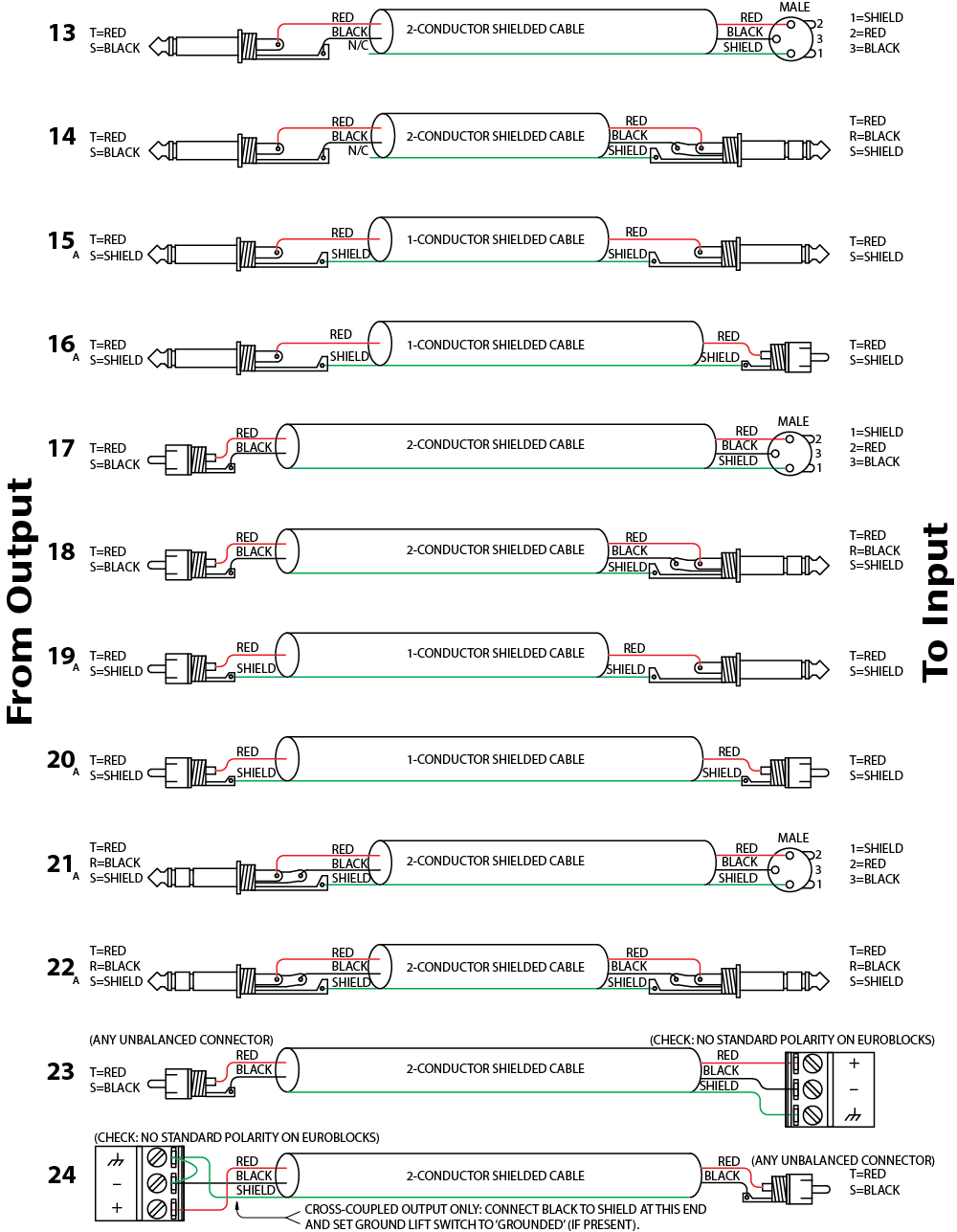
See Figure 4 for suggested cable assemblies for your particular interconnection needs. Find the appropriate output configuration (down the left side) and then match this with the correct input configuration (across the top of the page.) Then refer to the following wiring diagrams.
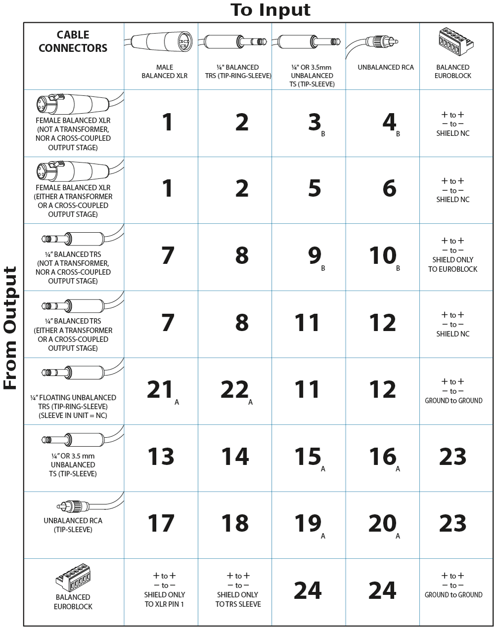
Note: (A) This configuration uses a standard "off-the-shelf" cable.
Note: (B) This configuration causes a 6 dB signal loss. Compensate by "turning the system up" 6 dB.
Many units come equipped with ground lift switches. In only a few cases can it be shown that a ground lift switch improves ground related noise. (Has a ground lift switch ever really worked for you?) In reality, the presence of a ground lift switch greatly reduces a unit's ability to be "properly" grounded and therefore immune to ground loop hums and buzzes. Ground lifts are simply another Band-Aid to try in case of grounding problems. It is, however, true that an entire system of properly grounded equipment, without ground lift switches, is guaranteed (yes guaranteed) to be hum free. The problem is most equipment is not (both internally and externally, AC system wise) grounded properly.
Most units with ground lifts are shipped so the unit is "grounded" -- meaning the chassis is connected to audio signal ground. (This should be the best and is the "safest" position for a ground lift switch.) If after hooking up your system it exhibits excessive hum or buzzing, there is an incompatibility somewhere in the system's grounding configuration. In addition to these special cable assemblies that may help, here are some more things to try:
During inspection, you may run across a 1/4" output called floating unbalanced, sometimes also called psuedo-balanced or quasi-balanced. In this configuration, the sleeve of the output stage is not connected inside the unit and the ring is connected (usually through a small resistor) to the audio signal ground. This allows the tip and ring to "appear" as an equal impedance, not-quite balanced output stage, even though the output circuitry is unbalanced.
Floating unbalanced often works to drive either a balanced or unbalanced input, depending if a TS or TRS standard cable is plugged into it. When it hums, a special cable is required. See drawings #11 and #12, and do not make the cross-coupled modification of tying the ring and sleeve together.
If you are unable to do things correctly (i.e. use fully balanced wiring with shields tied to the chassis at the point of entry, or transformer isolate all unbalanced signals from balanced signals) then there is no guarantee that a hum free interconnect can be achieved, nor is there a definite scheme that will assure noise-free operation in all configurations.
Band-Aid is a registered trademark of Johnson & Johnson
![]() "Sound System Interconnection" Download this note in PDF.
"Sound System Interconnection" Download this note in PDF.