Few would argue the necessity of equalizers for quality sound reinforcement systems. They are an essential tool that every sound person keeps in their bag of tricks for establishing high quality sound. Without equalizers the system is left without nearly enough controls to turn to try and correct for room difficulties, speaker anomalies, and individual performer preferences.
In 1982, Rane pioneered a new type of graphic equalizer called a Constant-Q Graphic Equalizer to solve one of the most annoying problems that plagued all previous 1/3-octave designs. Namely, that the bandwidth of the filters was a function of the slider position; only at the extreme boost/cut positions were the filter bandwidths truly 1/3-octave wide. At all modest boost/cut positions the filter bandwidths exceeded one octave. For true "graphic" operation, and real control of a system's frequency response, this was an unacceptable design.
The new Constant-Q graphic equalizer circuit topology allows true 1/3-octave bandwidth control at all slider positions. Finally, equalizers are available that are accurately "graphic" in the picture formed by their slider positions. Gone is the misleading picture formed by conventional designs: if a single slider is boosted 3 dB then only that 1/3-octave frequency band is being affected, unlike other equalizers where the real picture is over one octave wide.
The advantages of the Constant-Q design go far beyond yielding a more accurate picture; they provide a degree of adjustment never before possible. Crucial subtle refinements of frequency response are for the first time possible, allowing for an unequaled clarity of sound reproduction.
Equalizers fall into two very large categories: graphics and parametrics. Graphic equalizers further divide into two groups dominated respectively by 15 band 2/3-octave equalizers and 30 band 1/3-octave equalizers. Functionally, parametrics fall between 15 band and 30 band equalizers. The 15 band graphic equalizers offer great economy but very little flexibility or control. Parametrics give great control flexibility at an increased cost, but are limited to only being able to correct four, five or at most eight frequency spots per equalizer. The 30 band equalizer is the preferred choice by sound professionals at a cost equal to, or slightly higher than parametrics, but with the ease and convenience of being able to apply correction to 30 places.
Graphic equalizers get their name from the fact that the relative positions of the 15 or 30 sliders supposedly form a "graphic" picture of the frequency response correction being applied (that they do not, is why Rane developed Constant-Q equalizers.) Parametrics get their name from the fact that all three "parameters" of the filters are fully adjustable, i.e., center frequency, amplitude and bandwidth. In graphic equalizers, the center frequencies are fixed at standard ISO (International Standards Organization) locations; likewise, the bandwidths are normally set at either one, 2/3-octave, or 1/3-octave widths.
To understand the inherent problems with conventional equalizers and to follow the evolution of Rane's unique Constant-Q approach requires a brief review of equalizer filter fundamentals.
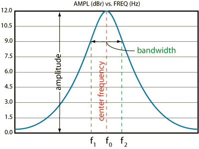
Figure 1. Bandpass Filter Parameters
As a review and to establish clear definitions of terminology, Figure 1 shows the frequency response of a typical equalizer filter.
Equalizer correction is accomplished by band-pass filters, each designed to function over a different range of frequencies. A filter is just like a sieve; it passes some things and blocks others. In this case it passes certain frequencies and blocks all others. A filter may be designed to pass just a single frequency, or it may pass all frequencies above or below a certain one, or it may pass only a specific band of frequencies. The latter is termed a bandpass filter.
Bandpass filters are characterized by three parameters as shown in Figure 1. Amplitude refers to the maximum gain through the filter and occurs at a specific center frequency, f0. The filter is said to have a certain bandwidth, defined as the span of frequencies between the points where the amplitude has decreased 3 dB with respect to that of the center frequency. The interpretation of Figure 1 proceeds as follows: The filter has a passband between frequencies f1 and f2 and an upper and lower stopband outside these frequencies. It has a gain of 12 dB (a gain of 4) at f0: so frequencies around f0 are made larger by a factor of about 4 while those frequencies significantly outside the f1-f2 window are not amplified at all. Bandwidth is usually expressed in octaves. One octave is a doubling of frequency; therefore a bandpass filter with passband boundary frequencies f1 and f2 of, say, 100 Hz and 200 Hz respectively, is said to be one octave wide. One-third octave is a 26% increase in frequency (21/3 = 1.26); therefore, boundary frequencies of 100 Hz and 126 Hz respectively would be 1/3-octave wide.
The Quality Factor, or "Q", of a filter is a close relative to bandwidth. It is defined to be the center frequency divided by the bandwidth in Hertz. For example, a filter centered at 1000 Hz that is 1/3-octave wide has -3dB frequencies located at 891 Hz and 1123 Hz respectively, yielding a bandwidth of 232 Hz. Q, therefore, is 1000 Hz divided by 232 Hz, or 4.31.
With suitable circuitry wrapped around it, a band-pass filter may be designed to give an adjustable amplitude characteristic that can be either boosted or cut. The frequency response of such a circuit appears as Figure 2 and forms the heart of any equalizer.
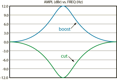
Figure 2. Typical Equalizer Response
If variable controls are put onto each of the three parameters described in Figure 1, a parametric equalizer is realized. The user now has individual control of where the center frequency is located, the width over which the filter will act, and amount of boost or cut.
The conventional variable-Q equalizer suffers from a great deal of filter overlap at low corrective settings (which gives it its "combining" characteristics) and a severe degradation of its bandwidth at high settings, making its performance very unpredictable.
Conventional graphics are overwhelmingly of one basic design, namely, LRC equalizers (Gyrators are LRC designs painted a different color -- more on this later). An LRC design gets its name from the need for an inductor (electronic abbreviation: "L"), a resistor (R) and a capacitor (C) for each filter section.
The problems inherent in any LRC design arise when the bandwidth determining factors are examined. As mentioned earlier, bandwidth and Q are intimately related. High Q's mean narrow bandwidths and vice versa. At the slider end points the Q of the filter is very high but at all intermediate slider positions it degrades. There is a different value of Q for every possible slider position. What this means is that the bandwidth of the filter is different for each slider position, being the narrowest at the extreme slider positions and becoming wider and wider as the slider is moved toward center. This is why a single slider on a conventional one-third octave equalizer affects over three times the bandwidth expected when boosting or cutting modest amounts.
Gyrators are solid-state equivalents to inductors and solve all of the really nasty problems inherent with real-world inductors. Inductors are big, bulky, heavy and expensive. They make marvelous antennas for hum pick-up and must be shielded and positioned very carefully if they are not to turn a wonderful design into a system full of hummingbirds. All of which adds more cost.
Gyrators are used therefore to replace the inductors in LRC designs. They allow for very cost-effective, easily designed equalizers. The only drawback is that they do not in any way alter the bandwidth versus slider position problem. Q is adversely affected by the slider position in exactly the same manner.
So called, "combining" filters are really a misnomer, since they are yet another manifestation of LRC equalizers. The name comes about in the manner that the individual LRC filter sections are summed together to obtain the final output.
Most commonly, the LRC network is duplicated 15 or more times, with all slider pots in parallel and tied to one master op amp. This indeed does work, although the intersection caused by all these parallel networks makes things a little squirrelly and must be compensated for by tweaking each section. A far better solution is to add one or more summing op amps and break up the chain into several series-parallel networks, or "combining" circuits, as they have become known. The end result is a much more predictable design, that gives a smoother resultant curve.
All of this is fine, it just has nothing to do with the bandwidth versus slider position problem. What is needed is a completely different approach -- one not based on LRC equalizer topology at all. A new design.
It should be obvious by now, that parametric equalizers must be based upon totally different topology than are graphic equalizers, since all three parameters are independently adjustable.
Well, some are and some are not.
Some parametrics (I will be kind and not name them) offer adjustment of amplitude, center frequency and bandwidth that are not independent. But since you can adjust each, they get away with it. Those parametrics that offer truly independent adjustment (and there are many) are indeed based on different topology. The heart of these designs is a bandpass section called a state-variable filter. A state-variable filter is one where all three parameters are separately adjustable. Notice the word is "separately", not "independently". Most state-variable designs allow center frequency to be independently adjusted, but require bandwidth and gain to be adjusted in a certain order. One of the ways around this dilemma is to do the amplitude function separate from the filter, thus allowing each filter section to have its gain fixed. Then, by clever selection of component values, both center frequency and bandwidth become independent from each other.
Parametrics offer such flexibility with such complexity that they can be their own worst enemy. Their complexity causes two serious drawbacks: cost and limited bands. With three controls per band, very few bands are possible per instrument -- typically, only four or five. Their flexibility can also be a mixed blessing: they are very difficult to use because you cannot, at a glance, tell where you are with regards to frequency position, degree of boost/cut, or bandwidth. Translating from 1/3-octave realtime analyzer readings to a parametric requires some intuitive concentration.
For all these reasons, 1/3-octave equalizers, with their graphical picture of boost/cut, fixed center frequencies, and narrow bandwidths offer the ultimate in control for quality sound systems.
If only someone would fix that damn bandwidth versus slider position problem!
The development of the Constant-Q graphic equalizer is the logical next step after reviewing and clearly understanding designs and problems of LRC equalizers and parametrics. It's the result of applying the very best parametric equalizers topology to graphic equalizers.
The filter sections are now totally isolated from the effects of the amplitude slide pots with respect to center frequency and bandwidth; allowing each filter to be designed for the precise center frequency and narrow bandwidth required. The result is unequaled freedom between bandwidth and slider position. A freedom to make subtle adjustments a reality without resorting to racks of parametrics or being forced to 1/6-octave graphic overkill.
But, does it work? Confucius say, "One picture...
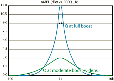
Figure 3. Conventional Graphic
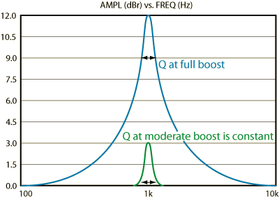
Figure 4. Constant-Q Graphic
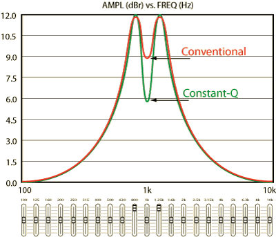
Figure 5. Alternate Sliders Boosted 6 dB
Figures 3, 4 and 5 nearly speak for themselves. In Figure 3, the results from a highly regarded, expensive, California-designed, graphic equalizer are shown. Note that the 1/3-octave wide bandwidth at the 12 dB boost position degrades drastically when only boosted 3 dB, while in Figure 4 the constant-Q graphic equalizer design holds its narrow bandwidth almost perfectly. For a really telling picture, look at Figure 5, where a very expensive import 1/3-octave graphic is shown with alternate sliders of 800 and 1.25 kHz boosted 12 dB (the 1 kHz slider is centered); compare the results to the constant-Q design under identical conditions. Which one is really a "graphic" equalizer?
The term "interpolating" equalizer is not used solely to confuse the uninitiated. It is so called because its design allows one to reach any frequency on or between ISO prescribed center frequencies. To interpolate is to come to a realization somewhere between two numbers or entities, and this is exactly what interpolating constant-Q equalizers do.
Realtime analyzers were designed to work with equalizers, or was it the other way around? In any event, there are now more ways to analyze a room than just with the realtime approach. If you are only concerned with the indications of a realtime analyzer, then it is not important to be able to dial in correction between the centers of the filters. However, if you can view anomalies in between, it should then be possible to adjust for these indications with the processing instrumentation. In light of this it is incumbent on the manufacturers of equalization products to allow this. Rane has done just that by designing interpolating constant-Q equalizers.
Such things as dual channel fourier analysis, MLSSA, and the TEF analyzer have changed the way audio professionals adjust a sound system. These new test devices make it possible for the sound system operator to view and correct deficiencies in the sound spectrum that are as narrow as a few cycles. This sort of critical evaluation is not possible with a realtime analyzer and should, therefore, change the way equalizer designers view their task.
The constant-Q equalizer bandwidth does not change with amplitude. Its fixed 1/3-octave bandwidth will, however, allow small ripples to develop between two adjacent bands, as seen in Figure 6. This ripple may fall at a frequency requiring adjustment as indicated by the sophisticated test equipment now being used. This occurrence may limit its usefulness in this application.
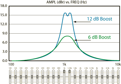
Figure 6. Constant-Q EQ with Two Adjacent Sliders Boosted 6 dB and 12 dB
You see a very small dip between the peaks at the center frequencies. This is the "ripple" that the interpolating equalizer avoids.
The interpolating equalizers from Rane are really another category of equalizer. This advancement in equalization provides the best of all of the three previously mentioned categories. Its filter bandwidths will not vary as its controls are adjusted. Its "filter combining" characteristics will not degrade when large amounts of correction are required, and its filters will interact predictably when two adjacent filters are used to reach a frequency between the ISO frequency centers.
In providing this flexibility, the actual bandwidths have been adjusted only slightly wider than that required by a conventional realtime. This assures the best possible convergence of two filters while maintaining a fixed, predictable bandwidth that is narrow enough to satisfy the needs of those using 1/3-octave realtime analyzers. Should one attempt to use two filters to adjust a node between center frequencies, the interpolating constant-Q equalizer will allow this without the ripple associated with normal constant-Q designs.
The term "combining" has been bandied about in the audio world for almost as long as there have been equalizers. The term is a bit of a misnomer in that the filters themselves do not combine. The resultant curve produced by an equalizer is a combination of the individual filter magnitudes which are set by the controls on the equalizer. The curve at the output will be such a combination, regardless of the design philosophy of the equalizer. The lack of combining attributed to the constant-Q devices as they have been known is purely a function of the bandwidth of their filters. The bandwidth of a constant-Q equalizer is fixed and the bandwidth of a conventional equalizer is not. Configuring a constant-Q equalizer for optimum filter combining will be the ideal. This provides optimum performance on and in between the ISO center frequencies.
Since these effects are a direct result of the filter bandwidth, any equalizer exhibiting variable bandwidth cannot be relied upon to perform predictably over its control range. Only an interpolating equalizer will deliver the necessary results at all times at all settings. There will be no degradation of bandwidth and no changes in adjacent filter summation -- just reliable performance.
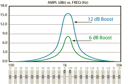
Figure 7. Interpolating EQ with Two Adjacent Sliders Boosted 6 dB and 12 dB
Comparing Figures 6 and 7 tells the story. Figure 7 was generated through an interpolating GE 30. Notice that the combined peak of the 800 Hz and 1 kHz filters are the same, level not withstanding. This is the kind of performance required under the scrutiny of today's test equipment and the ever more critical ears of modern humanity. The center frequency can be fine tuned, as in a parametric, by raising or lowering an adjacent band. The result will always be a smooth response.
Rane introduced constant-Q equalizers in the mid-eighties. Now, most equalizer manufacturers produce constant-Q models. When using a 1/3-octave analyzer, a constant-Q equalizer gives the best, most accurate results, and truly delivers "graphic" representation of the equalization curve with the front panel sliders. Actual use of an equalizer rarely (and shouldn't) require full boost or cut in any band, and the more realistic ±3 to ±6 dB corrections on a conventional equalizer requires over-compensating adjacent bands to arrive at the correct curve. What you see is what you get with a constant-Q.
The interpolated peak exhibited by Figure 7 satisfies the requirements of today's sophisticated measurement equipment. Simultaneous adjustment of any two adjacent sliders allows precise control of the response peak at frequencies between ISO standard points. By adjusting each slider up or down relative to each other, the peak may be moved to the right or left to give continuous coverage of all frequencies between the ISO boundaries. Control like a parametric, with the convenience of a graphic, without the trade-offs of a conventional equalizer. Only from Rane.
![]() "Exposing Equalizer Mythology"
"Exposing Equalizer Mythology"
![]() "Operator Adjustable Equalizers"
"Operator Adjustable Equalizers"
![]() "Perfect-Q, the Next Step in Graphic EQ Design"
"Perfect-Q, the Next Step in Graphic EQ Design"
![]() "Constant-Q Graphic Equalizers" This note as PDF.
"Constant-Q Graphic Equalizers" This note as PDF.