It is incorrect to state peak voltage levels in dBu. It is common but it is wrong.
It is wrong because the definition of dBu is a voltage reference point equal to 0.775 Vrms (derived from the old power standard of 0 dBm, which equals 1 mW into 600 Ω). Note that by definition it is an rms1 level, not a peak level.
1 “rms’’ is the mathematical abbreviation for root-mean-square, which is the effective value of a periodic electromagnetic wave, and equals the DC voltage that would produce the same power dissipation (heat) into a pure resistance. It is found by taking the square root of the mean (average) of the squares of a group of numbers (hence the name). If these numbers represent the voltage values of an audio signal taken at different times then they represent the effective level of that audio signal.
So, how do you correctly state peak voltages? Here are some suggestions from a couple of industry pros:
Ted Uzzle, Director of Contracting, Columbia College Chicago:
“dBu is clearly referenced to 0.774596669 V r.m.s., the square root of the product of 0.001 times 600. Neither average nor peak nor democratic nor republican nor Catholic nor Protestant nor Jewish nor Fluke nor Tektronix nor Hewlett-Packard voltages can be properly expressed in dBu. This is true whether the relationships are fixed, as with a sine wave, or constantly variable, as with speech or music. I would suggest the usage:
‘peaks XX dB above YY dBu’
as complete, correct, and self-explanatory. That phrase, in fact, well defines, the word ‘headroom,’ or anyway so says I.”
Tom Holman, TMH Corporation, and Professor at USC School of Cinematic Arts:
“When you change a B&K meter from rms to peak reading on a sine wave, the level goes up 3 dB, and that’s the way it should be. To be most precise we have to say:
'The maximum level of a sine wave that remains unclipped is XX Vpk, which corresponds to an rms level of +YY dBu.'”
Of course when dealing with real world audio signals, i.e., not sine waves, it gets a bit more complicated and involves what is called crest factor.
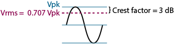
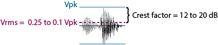
Crest factor is defined as the ratio of the peak (crest) value to the rms value of a waveform measured over a specified time interval. Sine waves have a crest factor of 1.4 (or 3 dB), since the peak value equals 1.414 times the rms value. Music has a wide crest factor of 4-10 (12 dB – 20 dB). This means that music peaks are 12 dB – 20 dB higher than the rms value — showing why headroom is so important in audio design — and why when you change a B&K meter (or any other brand rms and peak reading meter) from rms to peak reading on audio signals, the level goes up anywhere from 12 dB to 20 dB.
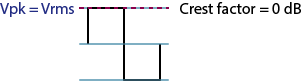
Note that a square wave represents the extreme where the rms and peak levels are the same, equaling a crest factor of one.
Wave Type |
Waveform |
Vrms = ? Vpk |
Crest Factor (Vpk / Vrms) |
Sine Wave |
|
1/√2 = 0.707 |
√2 = 1.414 = 3 dB |
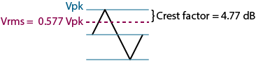
Triangle Wave |
|
1/√3 = 0.577 |
√3 = 1.732 = 4.77 dB |
Square Wave |
|
1/1 = 1.0 |
1.00 = 0 dB |
Audio |
|
0.25 to 0.1 |
4 to 10 = 12 dB to 20 dB |
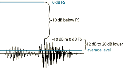
0 dBFS refers to a digital audio reference level equal to “Full Scale.” It is used in specifying A/D and D/A audio data converters. Full scale refers to the maximum peak voltage level possible before “digital clipping,” or digital overload (overs) of the data converter. The Full Scale value is fixed by the internal data converter design, and varies from model to model.
Full scale therefore is the maximum signal level resolvable by a data converter — either an A/D or D/A. It is determined by the DC reference voltage used by the converter. Since this is a DC level it is a brickwall limit with no way over. Therefore all signal levels expressed in terms of dBFS are peak levels, and expressed as negative numbers (since the maximum is 0 dBFS). They should never be expressed in dBu, but rather in plain-Jane dB. For example, a level equal to -10 dB re dBFS means that the peak level is 10 dB below the maximum peak level and if this is an audio signal then the average level is 12 dB - 20 dB lower. See diagram below.
The above describes the most popular usage, however it is technically incorrect.
The AES Information Document for Digital audio engineering – Guidelines for the use of the AES3 interface, AES-2id-2006 defines Full-Scale Amplitude as:
“the rms voltage that corresponds with a sine wave whose positive peak value reaches the maximum positive digital value and whose negative peak reaches one LSB greater than the minimum negative digital value.”
This means a full scale sine wave input would read +3 dBFS, and so would a full-scale square wave, and its rms value would equal +3 dBFS.
Further, AES Information Document for Digital audio engineering – Personal computer audio quality measurements, AES-6id-2006 defines Decibels, Full-scale (dB FS):
“Digital signal rms amplitude expressed as a level in decibels relative to full-scale amplitude (20 times the common logarithm of the amplitude over the full-scale amplitude [defined as the ‘rms amplitude of a 997 Hz sine wave in the digital domain whose positive peak value reaches the positive digital full scale, leaving the negative maximum code unused.’]). Note that dB FS expresses a signal level of a digital signal and should not be used to express the signal level of an analog signal.” [Bold italics added by author.]
The golden rule is to never express analog signal levels in terms of dBFS. Follow this and you will not confuse anyone.
The PPM (peak program meter) is an audio meter originally developed in Europe to accurately measure and display peak audio signals (as opposed to average audio signals, which use the VU meter). [While this is the popular belief, the meter does not actually measure “peaks.” It measures quasi-peaks based on an integration time of 10 ms—contrasting with a VU meter’s integration time of 300 ms, thus short peaks do not register on a PPM. Thanks to Richard L. Hess (www.richardhess.com) for this clarification].
The PPM augments the VU meter (originally called the VI or volume indicator; now archaic usage) and it is normal to find both in modern recording studios. The PPM is particularly valuable for digital audio recording or signal processing due to the critical monitoring required to prevent exceeding 0 dBFS and reducing overs.
Since all PPM signal levels are peak (by definition) no confusion should result. If further signal level information is desired then it should be expressed as explained in the first paragraph, i.e., the signal peaks XX dB above YY dBu.
Headroom vs. “Peakroom”
You can make a distinction between “headroom” and something that Pat Brown at Syn-Aud-Con calls “peakroom.” Here is the distinction that Pat makes:
Peakroom is the difference between clipping and your average signal level. This tells you how much room you have for your peaks.
Headroom is the difference between clipping and your maximum peak signal level. This tells you how much safety factor exists between your peaks and hard clipping.
For instance, a +4 dBu signal with 20 dB crest factor passing through a device that clips at +24 dBu has 20 dB of peakroom, but no headroom. A sine wave driving the same device to clip has 3 dB of peakroom but no headroom.
It is not a standard term, but it is sometimes useful to make this difference.
![]() "No Such Thing as Peak Volts dBu" Download this note in PDF.
"No Such Thing as Peak Volts dBu" Download this note in PDF.