In his landmark 1994 AES paper, Neil Muncy described a common equipment design error that allows current flowing on the shields of audio wiring to enter equipment and cause audible interference. He called this design error “the Pin 1 problem,” because it was an improper connection of the shield terminal, pin 1 in XLR connectors.
Cable shields are essentially an extension of the shielding enclosure of equipment, and they should be connected directly to that shielding enclosure. To make equipment cheaper to build, manufacturers started connecting cable shields to the circuit board’s common trace, then took that trace to the chassis. The problem is that any voltage drop across the wiring that is common to both the shield current and the circuit’s path to ground will be injected into the audio circuitry.
Shield currents include the noise currents coupled into ground by power line filters, potential differences between “ground” at opposing ends of long cable runs, and the shield acting as an antenna, picking up RF dimmer noise and other radio signals. It’s quite common to have AM, FM, and TV broadcast signals flowing on the shields of audio wiring.
Neil has observed that most RF interference to audio equipment is caused by a pin problem, and some recent research I’ve done has convinced me that he’s right.
Here’s the inside of a rather expensive condenser mic (Figure 1), the manufacturer of which has long insisted that the shields of mic cables must be connected to the shell in order to prevent RF interference. A quick look at the photo tells us why -- this mic has a screaming pin 1 problem at VHF frequencies!
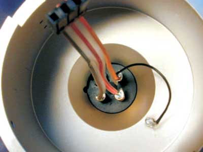
The black wire takes pin 1 to the body of the mic, and the orange wire takes pin 1 up to the circuit board. At audio frequencies, that works just fine. But at 56 MHz (the frequency of TV channel 2), the inductive reactance of the black wire is about 4Ω. If you try to use this mic in downtown Chicago with a properly wired mic cable, the shield current induced by Channel 2, Channel 5, and a bunch of FM broadcast stations causes enough voltage drop in the black wire (which the orange wire adds to the audio circuitry) that both the video and FM signals are clearly heard! Rick Chinn’s review of this mic several years ago for a magazine noted RF interference from TV stations, the closest of which were 13 miles away!
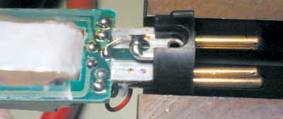
This mic has a pin 1 problem too (Figure 2), although not as severe -- it takes about 6 dB more RF to cause audible interference. Here, the shield goes to the chassis through the tiny wire connecting pin 1 to the broad tab holding the connector’s retaining screw. The combined length of that path is on the order of 1 cm, which results in about 2Ω of inductive reactance at 60 MHz. Again, circuit common is connected to pin 1 and sees the drop across the inductance. I was first alerted to the problem in this mic when I noticed that tightening the screw reduced the interference by about 3 dB!
The pin 1 problem works in reverse too -- any RF noise currents (digital clock noise, for example) flowing in that common impedance create a voltage drop that is coupled out to the shield. The shield, acts as an antenna and noise is radiated to nearby equipment and wiring. It’s not at all uncommon to see shield paths inside equipment 3-5 inches long! At 100 MHz, a 5" long wire is about 60 Ω! At 1 GHz, it’s about 600 Ω.
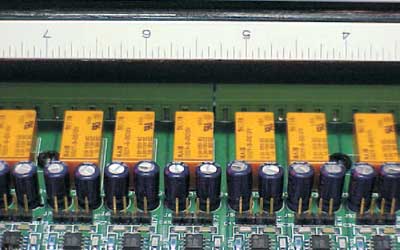
Figure 3 shows the rear panel connections to a DSP unit that has a bit of a noise problem. Looking behind the panel, we see the circuit traces go to the chassis via the two black screws at approximately the 4" and 7" points on the ruler that has been laid on top to show dimensions. All the incoming shields are bused together and go to the screws. These long leads (typically 2-4" with all the zigs and zags) are like open doors to radio frequency signals -- any current flowing on the shields radiates inside through antenna action, and noise inside the box is coupled out onto the shields, which also act as antennas.
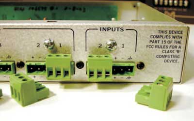
There are better ways to do this. Some manufacturers (Figure 4 shows a Rane product) provide a chassis screw next to pluggable strip connectors for proper termination of the shield. Inside, the signal leads go directly to RF filter networks.
In a series of tests I recently did on more than 45 condenser mics using standard XLR connectors, nearly all experienced serious interference from cell phones, and about one-third experienced significant interference from TV broadcast stations and/or my ham talkie.
The European EMC directive, implemented in the late 1990's, places limits on noise emissions from elec-tronic equipment sold in most European countries. It caused a lot of manufacturers to get EMC religion, and gave new life to RF engineers working in labs dedicated to verifying compliance. The engineers, working in these labs and those specializing in designing for good EMC performance, think in terms of RF immunity and computer/digital systems. Few have much practical experience with analog audio systems, and some of the design solutions they advance can cause us considerable grief -- especially the treatment of cable shields.
From an RF point of view, the shell of an XLR connector looks like it should work as the extension of the cable shield. For broadband RF immunity, it can be helpful to ground shields at every opportunity and carefully bond all grounded objects together at multiple points. Such a philosophy is the basis of the so-called “mesh” ground topology, and it can work well in installations where there’s little difference in potential between grounds at opposite ends of the audio paths. But power system leakage currents cause enough power-related shield current to flow in most real world installations to couple noise into the sound system if both ends of a cable shield are grounded.
Since the 1930’s, engineers have known that audio frequency noise coupling will be minimized with single point (star) grounding, while radio frequency noise coupling is minimized with multi-point (mesh) grounding. The solution is simple -- the shield of a balanced audio cable is connected to the shielding enclosure at the driving source, and to the shielding enclosure at the receiving end through a capacitor. It was easy to do this in the 40’s, when RF signals higher than 30 MHz were rarely encountered. It’s much tougher now, when the interference sources are strong RF signals from UHF cell phones and high power TV transmitters. Again, it’s series inductance that makes life difficult, this time the inductance of the capacitor’s wire leads. See Figures 5 and 6.
Feed-through capacitors have been a solution to this problem since the 1930’s. They mount in a circular hole in an enclosure. One “plate” of the capacitor is a wire going through the enclosure, while the other “plate” is a cylinder surrounding the wire and connected to the enclosure with a dielectric (insulation) between the plates. This circular construction minimizes the inductance through the capacitor to the chassis enclosure, while the wire coming into the chassis enclosure still has inductance. The resulting electrical circuit is an effective RF filter while it also prevents a hole in the shielding.
To provide the most effective shielding, both cable shields and the shells of connectors within equipment should be bonded to the chassis. (Retired Bell Labs engineer and EMC authority Henry Ott observes that if this connection is to the outside of the enclosure, skin effect will keep RF currents outside the enclosure as well.) But what about cable-mount connectors? To make the EMC engineering community happy, mic cables should tie the cable shield to the connector shell, but to make audio folks happy the shield should go only to pin 1. A few years ago, I proposed the concept of making a cylindrical connection to the shield in cable-mounted connectors much like that in a BNC connector, with that cylinder surrounded by a cylindrical dielectric that was itself surrounded by a cylindrical plate connected to the connector shell. Such construction would form a capacitor having very low series inductance, turning the XLR connector into a two-circuit feed-through capacitor. It would connect the shield to the shell at RF, while isolating it from the shell at audio frequencies and DC. When used on mic cable, the shield is also soldered to pin 1. When used at line level inputs in a rack, an installer could decide not to connect the shield to pin 1, but it would still be connected to the shell at RF through the capacitor.
Engineer Joanne Dow observed that if such a connector were to be used with a connection to pin 1, the capacitor and the series inductance to the chassis through pin 1 would form a parallel resonance, and suggested a ferrite bead surrounding pin 1 in the cable connector to lower the Q of the resonance.
It took a while for these ideas to germinate, but before long, engineers at Neutrik had begun work on a practical implementation (Figure 8), and by early 2002 had developed engineering prototypes. British consultant John Woodgate tested them in his lab, and I tested them both in my lab and in the field. The results met my expectations, and yielded an unexpected bonus -- they solved RF pin 1 problems, even when pin 1 was connected at both ends!
A simple circuit study shows why. Figure 7 shows a cable using the new connectors used with the mic shown in Figure 5. The concentric capacitor ties the shield to the mic shell with an inductance that is much lower than the wire inside the mic.
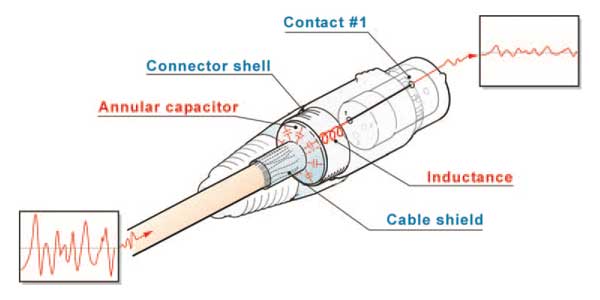
Not only that, but the ferrite bead around pin 1 inside the new connector adds series impedance to the path through pin 1, effectively disconnecting the shield from the pin 1 problem. Shield current thus divides, most of it taking the low impedance path through the capacitance to the shell, with very little flowing through pin 1. In effect, the new connector bypasses the problem!
But even this well engineered solution cannot be effective if mating connector shells don’t make good contact, or if the equipment connector shell is not bonded to the enclosure. I own a portable DAT machine that has a massive pin 1 problem, so much so that when it’s used with its own preamp with a dynamic mic in downtown Chicago the detected FM and TV stations are nearly as loud as an interviewer a foot from the mic. The new EMC connector completely eliminates the detected RF -- if I carefully push against the side of the connector to force the connector shells to make contact. But without that pressure, the shells can lose contact and the RF interference returns! And the new connector doesn’t help a popular mixer with a serious RF pin 1 problem, because the equipment connector shell is not connected to the enclosure!
Now that I’ve been alerted to them, these connector shell mating problems are turning out to be more prevalent than any of us would have suspected. It appears not to be limited to the use of off-brand or pirated connectors -- it shows up on connectors that have been verified to have come from the same manufacturer! I’ve also seen it in connectors built into very good quality preamps and mics from a variety of manufacturers. So far, the list includes Audio-Technica, Mackie, Neumann, Sound Devices, and Tascam.
![]() "Pin 1 Revisited" This note in PDF.
"Pin 1 Revisited" This note in PDF.