Knowledge Base
Unity Gain and Impedance Matching: Strange Bedfellows
Unity Gain and Impedance Matching: Strange Bedfellows
Dennis Bohn, Rane Corporation
RaneNote 124 written 1991; last revised 9/97
- Unity Gain and Balancing
- Impedance Matching
- Cross-Coupled Output Stages
Introduction
This note discusses the pitfalls (often subtle) of our industry's failure to define and standardize what "unity gain" means, and the conditions necessary to measure it. It further discusses how people improperly use one piece of misinformation (impedance matching) to correct for this lack of standardization. All done, without knowing discrepancies exist between different pieces of equipment, and without knowing impedance matching is unnecessary, signal degrading, and wasteful.
For me, it began with a phone call. The caller said he wanted to know our output impedance so he could add the proper load impedance.
"Why would you want to do such a thing?" I asked.
"Because I want to maintain unity gain through each piece of signal processing gear," he replied.
That gave me pause. Then I laughed and realized what he was doing right, and what he was doing wrong.
The problem stems from another case of our industry working without proper guidelines and standards. This one involves the conditions used to establish unity gain. Lately, the popular trend of including unity gain detent points and reference marks only aggravates things.
This Note identifies and explains the problem. Once understood, the solution becomes easy -- and it doesn't involve impedance matching.
Unity Does Not Always Equal One
It begins with an understanding of unity gain. Simple enough. Ask anyone and they will tell you unity gain means that if I put, say, 1 volt in, I get 1 volt out, i.e., a gain of one, or unity. Nothing could be easier. That is until that same someone asks the question,
"Is that unity gain balanced, or unbalanced?"
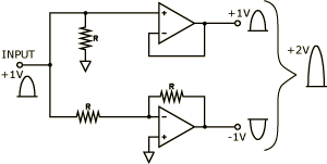
Herein lies the problem. Today we find that many (most?) pro audio signal processors have a gain difference of 6 dB between unbalanced and balanced out (exceptions to this are units with output transformers, or cross-coupled output stages -- see Appendix). This x2 difference results from differentially driving the line. Figure 1 shows how an input signal drives one side of the line positively and the other side negatively (each line driving amplifier has a gain of one, but together they yield a gain a two). For example, a +1 volt peak AC input signal drives one side to +1 volt while simultaneously driving the other side to -1 volt. This gives a balanced output level of +2 volts peak (the difference between +1 volt and -1 volt). Alternatively, that same input signal drives an unbalanced line to +1 volt peak. Thus, there is a 6 dB disparity between an unbalanced and a balanced output -- a gain difference factor of two.

Figure 1. Differential line driving circuit
No Standards
This brings us to the part about no standards. Without a standard defining the specified conditions for unity gain, manufacturers make their own decision as to what "unity gain" means. For one, it means 1 volt in gives 1 volt out unbalanced, and 2 volts out balanced. For another, it means 1 volt in gives 1 volt out balanced, and 1/2 volt out unbalanced. For yet others, it means 1 volt in gives 1 volt out (using transformers), or 2 volts out (using cross-coupled stages), either balanced or unbalanced. Very confusing.
Figure 2 shows how this creates problems. Here different definitions result in a gain of 12 dB, with all controls seemingly set for unity.

Figure 2. Example of signal increase due to different unity gain definitions
Impedance Matching
Impedance matching went out with vacuum tubes, Edsels and beehive hairdos. Modern transistor and op-amp stages do not require impedance matching. If done, impedance matching degrades audio performance.
Modern solid-state devices transfer voltage between products, not power. Optimum power transfer requires impedance matching. Optimum voltage transfer does not. Today's products have high input impedances and low output impedances. These are compatible with each other. Low impedance output stages drive high impedance input stages. This way, there is no loading, or signal loss, between stages. No longer concerned about the transfer of power, today's low output/high input impedances allow the almost lossless transfer of signal voltages.
What then, does impedance matching have to do with unity gain? Well, it shouldn't have anything to do with it. But because of different manufacturer's definitions, it is one way (brute force) of correcting gain discrepancies between products. Impedance matching introduces a 6 dB pad between units. Let's see how this works.
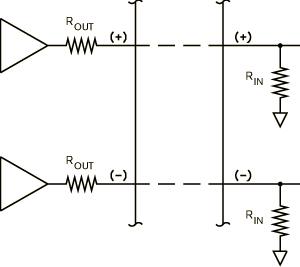
Look at Figure 3. Here we see a real world interface between two units. The positive and negative outputs of the driving unit have an output impedance labeled ROUT. Each input has an impedance labeled RIN. Typically these are around 100 ohms for ROUT and 20k ohms for RIN. Georg Ohm taught us that 100 ohms driving 20k ohms (looking only at one side for simplicity) creates a voltage divider, but a very small one (-0.04 dB). This illustrates the above point about achieving almost perfect voltage transfer, if impedance matching is not done.

Figure 3. Balanced wiring interconnection between units
If it is done, you lose half your signal. Here's how: impedance matching these units involves adding 100 ohm resistors (equal to ROUT) to each input (paralleling RIN). The new input impedance now becomes essentially the same as the output impedance (100 ohms in parallel with 20k ohms equals 99.5 ohms), therefore matching. Applying Ohm's law to this new circuit tells us that 100 ohms driving 100 ohms creates a voltage divider of 1/2. That is, 1/2 of our signal drops across ROUT and 1/2 drops across RIN, for a voltage loss of 6 dB. We lose half our signal in heat across ROUT. Not a terribly desirable thing to do; yet, it does fix our unity gain problem.
Back to Figure 2. By selectively impedance matching only between Units A and B, we introduce a 6 dB pad. This cancels the 6 dB gain resulting from using balanced outputs with this unit. This changes the output of Unit A to ± 1/2 V, or +1 V balanced. Since Unit B already is unity gain balanced, then we do not impedance match, and its output is also ± 1/2 V. We do impedance match Unit C's output and now Unit C passes this +1 V signal to its output as ± 1/2 V, and finally we get a true unity gain result from all three boxes. One volt in, produces one volt out -- balanced.
Preferred Alternative to Impedance Matching
The preferred alternative to impedance matching is ridiculously easy -- turn the level control down 6 dB. Of course this means the unity gain mark, or detent position, loses its meaning, but this is far better than losing half your signal.
Many users do not view this issue as a problem. There are so many other variables that require turning level controls up or down that this just becomes part of the overall system gain setting. Most units have sufficient headroom to allow for an unexpected 6 dB of gain without hurting anything.
Besides, the unity gain mark/detent is only a reference point. The whole reason manufacturers give you level controls, is to allow setting the gain you need for your system. If it were important for them to remain at unity, they would not be there. They are yours. You paid for them. Use them.
Summary
Unity gain and impedance matching: a strange dichotomy. One solves the other, but badly.
Impedance matching is not necessary and creates many ills. It reduces signal levels and dynamic range by 6 dB (and possibly signal-to-noise by the same amount). The large currents necessary to drive the low matching-impedance usually degrades total harmonic distortion. And the extra current means excess heat and strain on the power supply, creating a potentially unreliable system.
Simply turning the level control down (or up, as the situation dictates), is the best solution for unity gain disparities.
Appendix: Understanding Cross-Coupled Output Stages
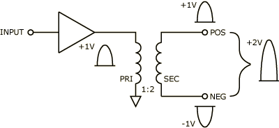
Cross-coupled output stages have been around for a long time [1]. So has their marketing rhetoric. Some of the many grand claims are even true. Understanding cross-coupled output stages begins with the following: The only purpose of cross-coupling techniques is to mimic an output transformer under unbalanced conditions. They offer no advantages over conventional designs when used balanced. Understanding cross-coupled circuitry begins with an understanding of output transformers (Figure 4). Here we see a typical configuration. The output amplifier drives the primary winding of the transformer (with one side grounded), and the secondary winding floats (no ground reference) to produce the positive and negative output legs of the signal. An output transformer with a turns ratio of 1:2 (normal), produces a 2 volt output signal for a 1 volt input signal, i.e., there exists a difference of potential between the two output leads of 2 volts. The diagram shows how a 1 volt peak input signal produces ±1 volt peak output signals (relative to ground), or a differential floating output of 2 volts peak. (Alternatively, two op-amps could differentially drive the primary; and use a turns ratio of 1:1 to produce the same results.)

Figure 4. Balancing output transformer
So, 1 volt in, produces 2 volts out -- a gain of 6 dB. Simple. Note that because the output signal develops across the secondary winding, it does not matter whether one side is grounded or not. Grounding one side gives the same 2 volts output. Only this time it references to ground instead of floating. There is no gain change between balanced and unbalanced operation of output transformers.
Contrast this with the active output stage of Figure 1. Here, grounding one side reduces the output from 2 volts to 1 volt. Though this is a one time gain reduction (correctable by increasing the level 6 dB), it bothers some. Mark off points.
Of more concern is the 6 dB lost of headroom. A desirable aspect of differentially driving interconnecting lines is the ability to get 6 dB more output level from the same power supply rails. Most audio products use op-amps running from ±15 volt rails. A single op-amp drives an unbalanced line to around ±11 volts peak (+20 dBu). Using two op-amps to drive the line differentially doubles this to ±22 volts peak (one goes positive, while the other goes negative), a value equal to +26 dBu. Mark off more points for loss of headroom.
Mark off even more points for potential distortion (depends on op-amps, and exact configuration), oscillation, and failure, resulting from asking one side to drive a short (the result of grounding one side for unbalanced operation).
These three things: 6 dB loss of gain, 6 dB loss of headroom, and the questionable practice of allowing an op-amp to drive a short, sparked creation of the cross-coupled output stage. It solves two out of three.
Cross-coupled output stages do two things active differential output stages do not. They maintain the same gain either balanced or unbalanced. And they protect themselves from having to drive a short. But they still have 6 dB loss of headroom.
A point not understood by many users. They believe that cross-coupled output stages behave exactly like transformers. Not true. They have the same headroom limitation as all op-amp designs operating from ±15 volt power supplies. (Some equipment uses ±18 volts, but this only results in a 2 dB difference for unbalanced.)
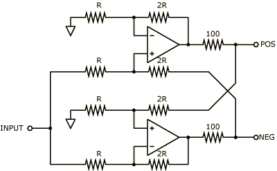
MCI's original design [1] appears in Figure 5. MCI used two op-amps, wired such that the opposite output subtracted from twice the input signal (not particularly obvious, but true). That way, each side's gain looks like a gain of one for balanced operation, i.e., 1 volt in, gives ±1 volt out. Yet shorting one side (running unbalanced) gives a gain of two (nothing to subtract).

Figure 5. MCI cross-coupled output circuit [1].
Since cross-coupled and normal differential output stages use essentially the same parts (and therefore cost the same), a fair question is why don't you see more of the former? The answer lies in the perils of positive feedback.
Inherent to the operation of cross-coupled output stages is positive feedback. The subtraction process created by cross-coupling opposite outputs, has an undesirable side effect of being positive feedback. Because of this, op-amp matching, resistor ratio matching and temperature compensation becomes critical. If not done properly, cross-coupled stages drift and eventually latch-up to the supply rails. (This is why you see so many variations of Figure 5, with all sorts of excess baggage glued on. Things like capacitive-coupled AC feedback, fixed loading resistors, high-frequency gain roll off capacitors, offset trims, etc.) The difficulty in controlling these parameters in high volume production, leads most manufacturers to abandon its use.
Recently, Analog Devices helped solve these problems by putting all the elements into one integrated circuit [2]. Their monolithic IC version (which Rane uses in select products) operates on the same principles as MCI's, although Analog Devices uses three op-amps to drive the input differentially. Here precise control and laser trimming guarantees stable performance, and opens up a new chapter in cross-coupled output stage use.
References
- T. Hay, "Differential Technology in Recording Consoles and the Impact of Transformerless Circuitry on Grounding Technique," presented at the 67th Convention of the Audio Engineering Society, J. Audio Eng. Soc. (Abstracts), vol. 28, p. 924 (Dec. 1980).
- "SSM-2142 Balanced Line Driver," Audio/Video Reference Manual, pp. 7-139 (Analog Devices, Norwood, MA, 1992).
Reproduced with permission from S&VC, vol. 8, no. 9, Sept. 20, 1990, pp. 10-20.
![]() "Unity Gain and Impedance Matching: Strange Bedfellows" This note in PDF.
"Unity Gain and Impedance Matching: Strange Bedfellows" This note in PDF.