Knowledge Base
Cost-Effective Noise Masking Systems
Cost-Effective Noise Masking Systems
Dennis Bohn, Terry Pennington, Roy Gill, Michael Rollins, Jeff Davies, Chris Duncan, Rane Corporation
RaneNote 116 written 1987; last revised 3/13
- Zones and Speaker Arrays
- Halogen Solution
Introduction
As the popularity of noise masking systems grows, so too does the cost of the equipment to implement it. However, like other sound system needs, Rane products can contribute a great deal to the cost-effectiveness of noise masking systems without sacrificing reliability or operational requirements.
Properly designed noise masking systems are an art form unto themselves. Their requirements far exceed what can be accomplished in this short space. The purpose of this note is to introduce noise masking designers to Rane products useful in their craft.
Figure 1. Pink Noise Spectrum
Basic System
Figure 2 illustrates the internal functional blocks of a typical noise masking generator. Connecting the system requires only patching the pink noise to the equalizer input, then connect the distribution and amplification electronics to the output of the equalizer. The downstream electronics may be in the form of a Rane SM26S to provide the necessary splits and level controls for individual zones, followed by a Rane MA 4 power amplifier. The output of the amplifier may then be fed directly to low impedance loudspeakers or to a constant voltage transformer system such as the Rane MT 4 Multichannel Transformer kit. In any event, the result is an extremely cost-effective noise masking system with a minimum of components. Figure 3 depicts such a system.
Figure 2. Typical Noise Masking Generator
Figure 3. Basic Noise Masking System Example
Multiple Array Noise Masking
Simple noise masking systems use one equalized noise generator, distributing the shaped noise throughout the ceiling array. While cost effective, these simple systems too often are, themselves, a distraction. When this happens, the system gets switched off and the customer feels noise masking doesn't work and they wasted their money.
The evolution of successful noise masking produced the following guidelines (from "Acoustics of Open Plan Rooms," by Rollins Brook and "Sound System Design," by Chris Foreman in Glen Ballou, Ed., Handbook For Sound Engineers [Howard W. Sams & Co, Indianapolis, 1987]) for creating unnoticeable, yet very effective systems:
- Use three carefully equalized noise sources
- Interlace noise sources driving speaker arrays
- Disperse noise evenly in all areas (±2 dB)
- Use adequate amplification to avoid clipping
- Use separate EQ for the paging source
- Do not attenuate noise during paging
These guidelines result in a fairly complex and expensive system. Luckily, Rane products can help reduce both.
The most random signal results from the use of exactly three noise sources (more do not add more). This way, no two adjacent speakers emit the same sound. Each neighbor produces a randomly different sound. Experience has shown this approach creates the least distracting and most effective masking.
A non-irritating and successful noise source mimics the shape and range of normal speech. This means a maximum frequency range of about 200 Hz to 5 kHz, with an overall rolloff of 5-6 dB per octave beginning at 200 Hz and extending to around 5 kHz.
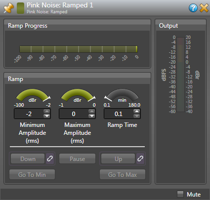
Thanks to DSP, a system can be assembled with greater flexibility and less expense than in the past. A HAL3s contains the mic preamp, pink noise sources, equalization, and matrix mixer (see Figure 4). As a bonus, you have a couple extra inputs for music or paging that could be switched on when you don't need the noise masking. The HAL3 is also remote-controllable with DR Remotes providing source selection and levels in each zone. The Halogen processing map is shown in Figure 6a with the required blocks for noise masking, block details are in 6b. Easily customizable, of course.
Figure 4. Multiple Array Noise Masking System Example
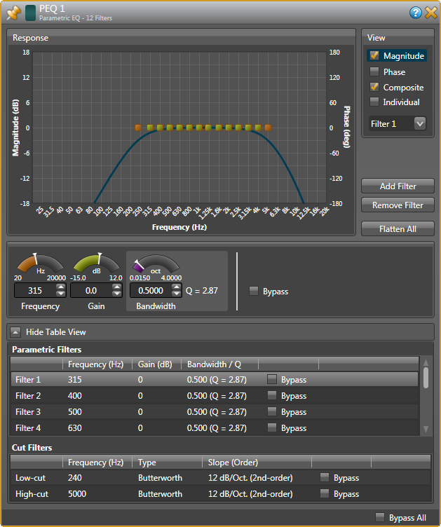
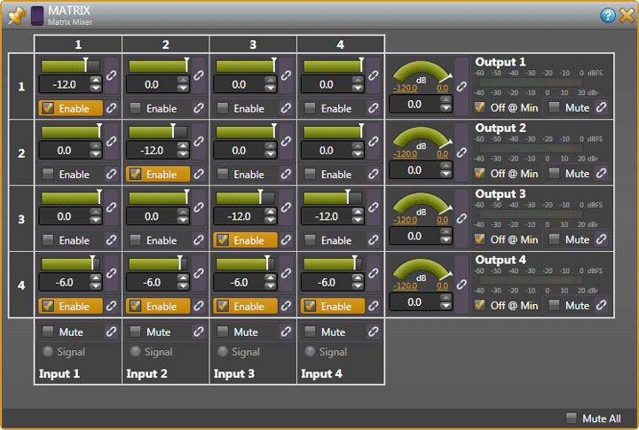
To start, set the Parametric EQ blocks after the pink noise. Set the Low Cut Filter to 240 Hz and the High Cut Filters to 5000 Hz. You might not need any more EQ than that, but additional filters may be used for room and speaker compensation. You may want to add a Feedback Eliminator block for the microphone if that potential exists. The Matrix Mixer block is set to 4 in, 4 out. Assign the mic to all outputs while routing the noise generators to A, B, and C. The extra 'Mic Only' output could page the lobby or outdoor area without the noise.
An MA 4 / MT 4 combination drives the ceiling array. The outputs drive the loudspeakers in an interlaced array as shown by Figure 5. No two adjacent speakers receive the same source. This is not the wiring nightmare it first appears. Notice that the speakers still wire daisychained, just diagonal instead of straight.
The noise must be as uniform as possible throughout the office environment. This demands lots of speakers. The most successful systems extend the noise signal into ancillary areas (storage rooms, copying/FAX centers, closets, etc.) adding even more speakers.
Figure 5. Noise Masking Ceiling Array
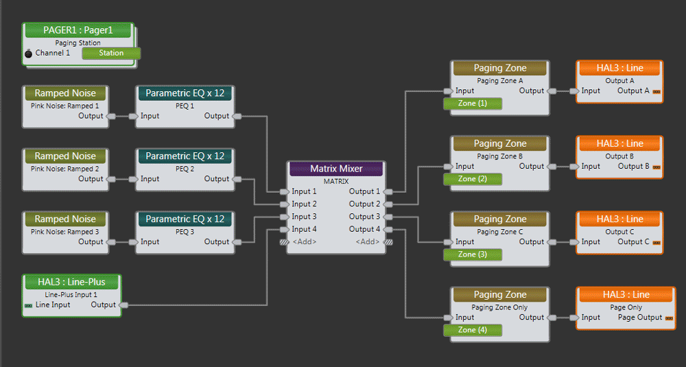
Figure 6a. Halogen Processing Map for Noise Masking with the HAL3s.
Figure 6b (below). Processing block details.
 Halogen Noise Masking configuration files download for the HAL3 and HAL3s.
Reference
"Acoustics of Open Plan Rooms," by Rollins Brook and "Sound System Design", by Chris Foreman in Glen Ballou, Ed., Handbook For Sound Engineers, Howard W. Sams & Co, Indianapolis, 1987.
 "Cost-Effective Noise-Masking Systems" This note in PDF.